Overview
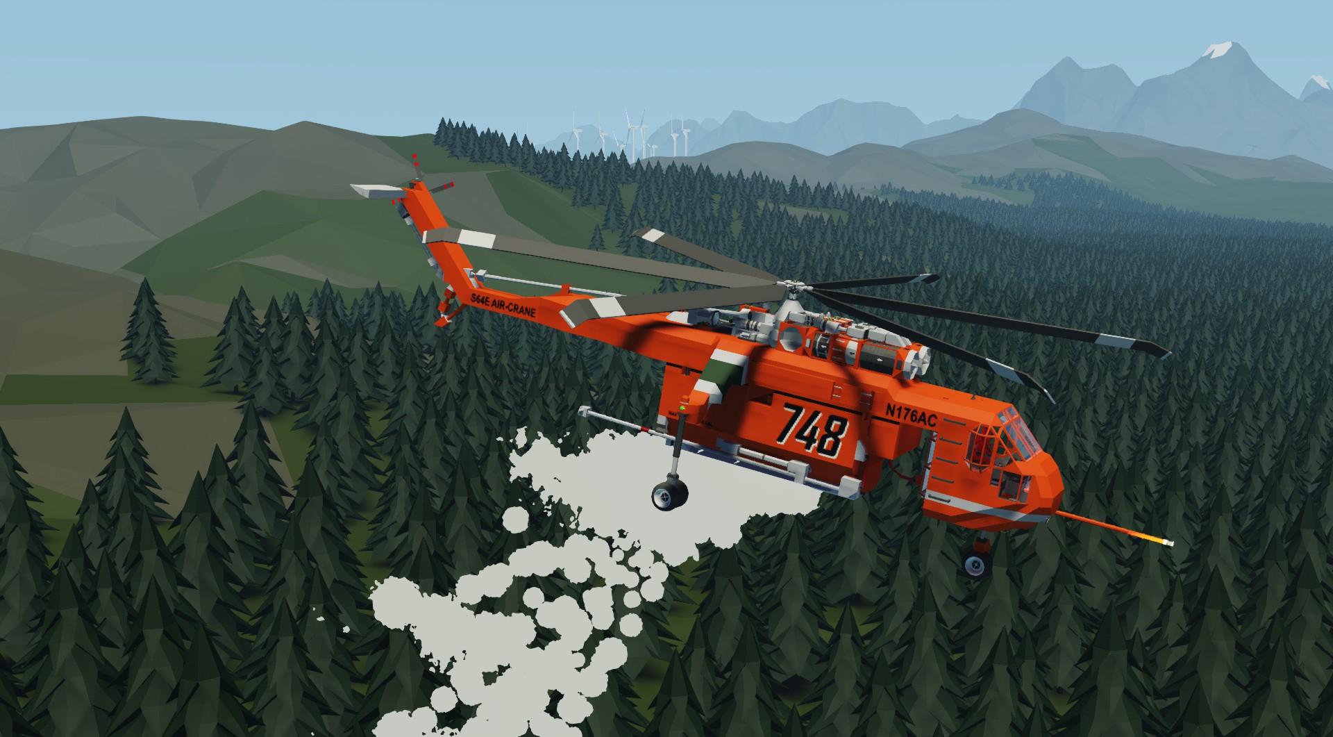
A brief overview of the helicopter as a whole and its systems presented in the model.
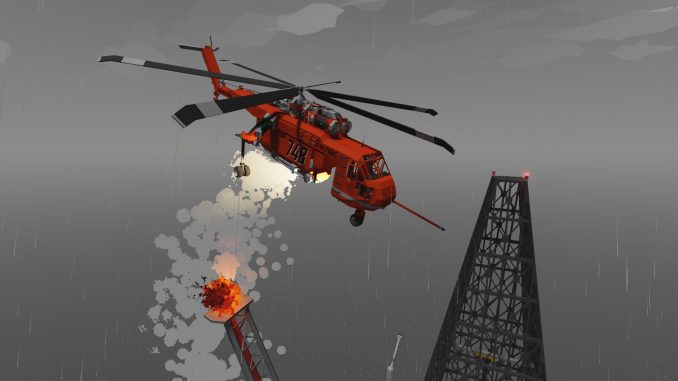
Sikorsky S-64, production number 003. This is the oldest of the ones which are running, was built in 1962, crashed in 1974 and restored. Standard painting, standard set of equipment, both for extinguishing fires and for transporting goods.
The maximum take-off weight of the first helicopters was 47,000 pounds (over 21 tons). The dry weight of the helicopter is just over 10 tons. The carrying capacity, it would seem, is about 11 tons, but 4 tons of fuel must be taken into account. The total weight of the cargo that could be lifted in the nominal mode was only about 7 tons, therefore the carrying capacity in the game for a temperature of +15 and an altitude above sea level is just 7 tons. If the regime is exceeded, you can raise more, but this is fraught with disasters.
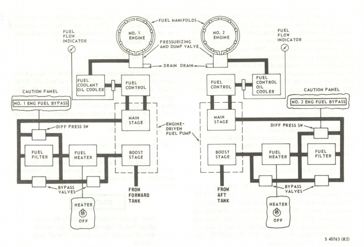
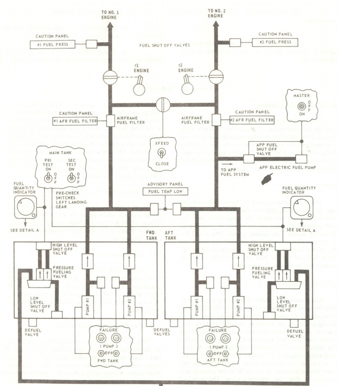
The operation of the engine and fuel system is simulated according to real schemes. The helicopter has three fuel tanks, 6 booster fuel pumps, two main fuel pumps, two independent fuel feed circuits with the possibility of cross-feeding.
The electrical circuit also corresponds to the real one both in design and functionally. Consists of a main DC bus (24 VDC) and two AC buses (115 VAC). The DC bus is connected to the AC bus through an inverter in one direction, and through two rectifiers in the other. The AC buses are interconnected through a monitor relay, which allows one bus to be powered from another.
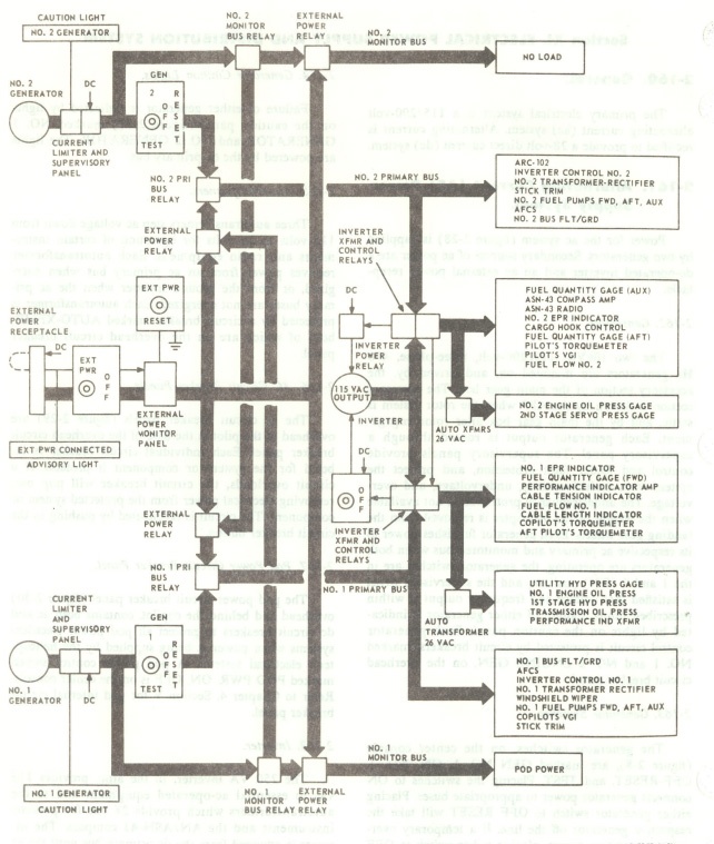
The hydraulics are also simulated in full, but for some reason my manual is missing a schematic diagram.
————–
Naturally, the model is still largely simplified for the sake of playability and optimization. For example, there is no simulation of fatal breakdowns that leave no chance of surviving. The tail rotor transmission has not been modeled. No pneumatic wheel brakes, no cockpit heater simulation, no system test procedures.
It seems to me that adding this set would reduce the already excessive complexity to a generally unplayable state, therefore – it is as it is. Enjoy.
Power panel
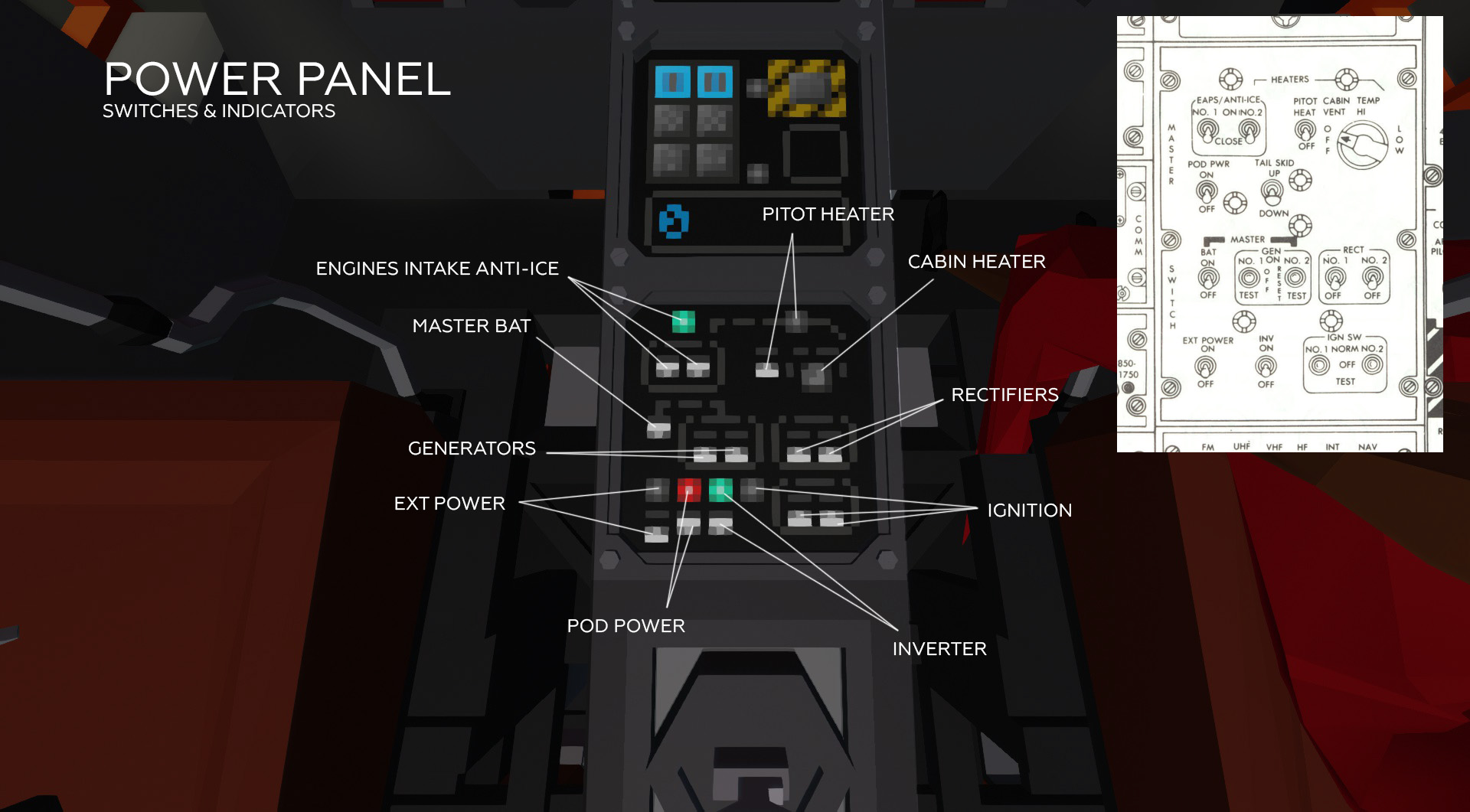
The panel is powered from the main DC bus.
1. Master bat – main battery relay. Provides 28 volt power to the DC bus.
2. Inverter – takes 28 volts from the DC bus and transforms to 115 volts primary AC bus. It turns off automatically in case of generators or rectifiers going online, abnormally – in case of breakdown.
3. Generators – Two generators driven by the transmission auxiliary output. Provide power to the primary and secondary AC bus, respectively. In case of a breakdown, power is not given.
4. Rectifiers – two rectifiers. Converts 115 volts from the first and second AC buses to 28 volts DC. In fact, they work in the opposite direction to the inverter, so turning on the rectifiers turns off the inverter. In case of breakdowns, they break.
5. Ignition – engines ignition modules. Powered by DC bus. They work only with a starters on.
—————-
Under no circumstances should the ignition be allowed to run continuously for more than 3 minutes. Break for cooling – 2 minutes.
—————-
that means if the engine does not start for some reason, the ignition modules will burn out during continuous attempts to restart.
The control relays and the modules itself may be damaged.
6. Engines intake anti-ice – heating the engine air intakes. The control lamp lights up if at least one of the heaters is on. Hot air for heating is taken from the compressors, so heating does not work with the engine off.
Possible breakdown of the control relays. The valves are powered from the DC bus.
7. Pitot heater – heating the air pressure receiver (Pitot tube). The receiver freezes in temperatures below 0 and high humidity, in the presence of wind; altimeter, variometer and speedometer readings become inadequate. The control lamp is on only in case of correct operation of the heater. Powered by DC bus.
—————-
Usage at >0 C temperatures causes overheating and breakage.
—————-
Possible breakdown of the control relay and breakdown of the heater itself.
8. Cabin heater – heats the cabin. Possible breakdown of the control relay. In reality, it is powered by a separate kerosene stove, in the game – from the DC bus.
9. Pod power – power supply to the cargo equipment. Possible breakdown of the control relay.
10. Ext power – external power connection. The connector is located on the right side of the cab bottom. Doesn’t break.
AFCS panel
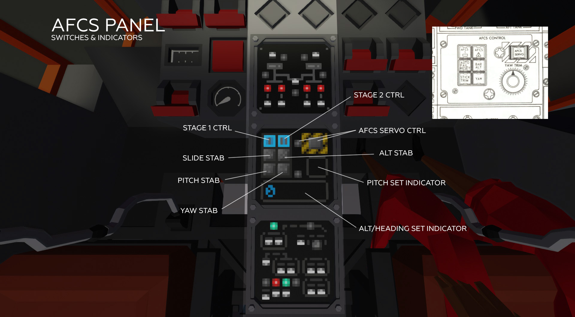
1. Stage 1/2 ctrl – valve control of pumps 1 and 2 of hydraulic systems. In the event of a breakdown, the pumps stop pumping.
2. AFCS servo ctrl – AFCS control. In the event of a breakdown, the AFCS begins to spontaneously turn on and off, seriously complicating control.
3. Alt stab – Barometric altitude stabilization . Duplicated by the "1" button on the keyboard.
4. Slide stab – Compensation for side drift.
5. Yaw stab – Azimuth stabilization. Duplicated by the "2" button on the keyboard.
6. Pitch stab – Pitch stabilization. Actually cruise control. Duplicated by the "3" button on the keyboard. Buttons "4" and "5" decrease or increase speed.
7. Alt / heading set indicator – shows the set altitude in feet and azimuth in degrees. To switch between readings, press the indicator. The autopilot maintains altitude with an accuracy of + – 10 feet.
8. Pitch set indicator – shows the set dive angle, actually – the desired flight speed.
Fuel panel, radio, auxiliary equipment
Radio [/ b]
The radio is powered from the second AC bus.
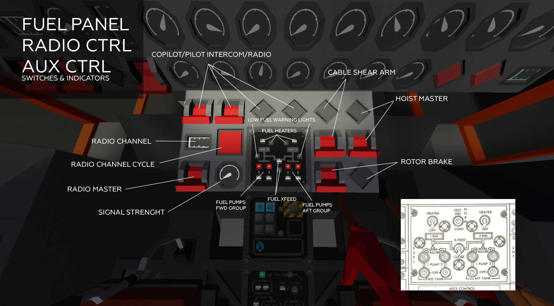
1. Radio master – turns on / off the radio. May break.
2. Signal strenght – the strength of the received signal.
3. Radio channel – receive / transmit channel from 0 to 8.
4. Radio channel cycle – channel switching button.
5. Pilot / copilot intercom / radio – in the off position of the toggle switches, the communication works in intercom mode, ie. between the crew members. When switched on, communication works in radio mode, i.e. communication with the ground or other machines. In transmission mode, the corresponding lamp comes on when LMB is pressed.
Fuel [/ b]
1. Fuel booster pumps fwd / aft group – control of the front / rear group fuel pumps. Each group is powered only from the corresponding tank and supplies fuel only to its own engine. The front group of pumps is powered from the first AC bus, the second from the second.
The emergency lights come on in the event of a drop in fuel pressure in the pump itself. Failure can be in the control relays, or in the pumps themselves.
2. Fuel xfeed – fuel cross feed valve. Allows feeding both engines from one tank and one group of pumps. The control relay may break.
The valve is powered from the DC bus.
3. Fuel heaters – fuel system heaters. At low temperatures, water in the fuel can freeze and clog the fuel filters with ice, which leads to a drop in pressure and, as a result, power. If the filters become too clogged, the bypass valve opens and fuel enters the engine bypassing the filter, leading to increased wear and the risk of breakage. In this case, # 1/2 F BPS lights on the warning panel will light up. Fuel heaters draw hot air from the compressors.
Turning on the heating at positive temperatures is prohibited by the instructions and leads to wear and damage to the heaters. The heating does not work with the engine off.
Clearing the system of ice takes some time, up to several minutes.
The heater valves are powered from the DC bus.
Auxiliary[/ b]
1. Cable shear arm – control of the cable cutting system. In the on state, the red light flashes, the system is ready to drop the load by pressing the "6" button on any seat.
Because in the game mechanics, the cable cannot be cut, so implemented by disconnecting the winch magnets and cargo connectors. Can’t break.
2. Hoist master – power supply of the winch. Can’t break.
3. Rotor brake – control of the rotor brake. It turns on only when the N1 levers of both motors are in position <40, and the rotor speed is less than 33%. Power is supplied from the auxiliary hydraulic system. If the pressure in the system is insufficient, proper braking will not occur. If the rotor does not stop within 20 seconds, the brake must be disengaged and the cause must be found out, otherwise the brake will wear out excessively and may break.
The control lamp lights up in all cases when the toggle switch is on. Actual brake operation is monitored by a warning lamp on the caution advisory panel.
Main instruments panel
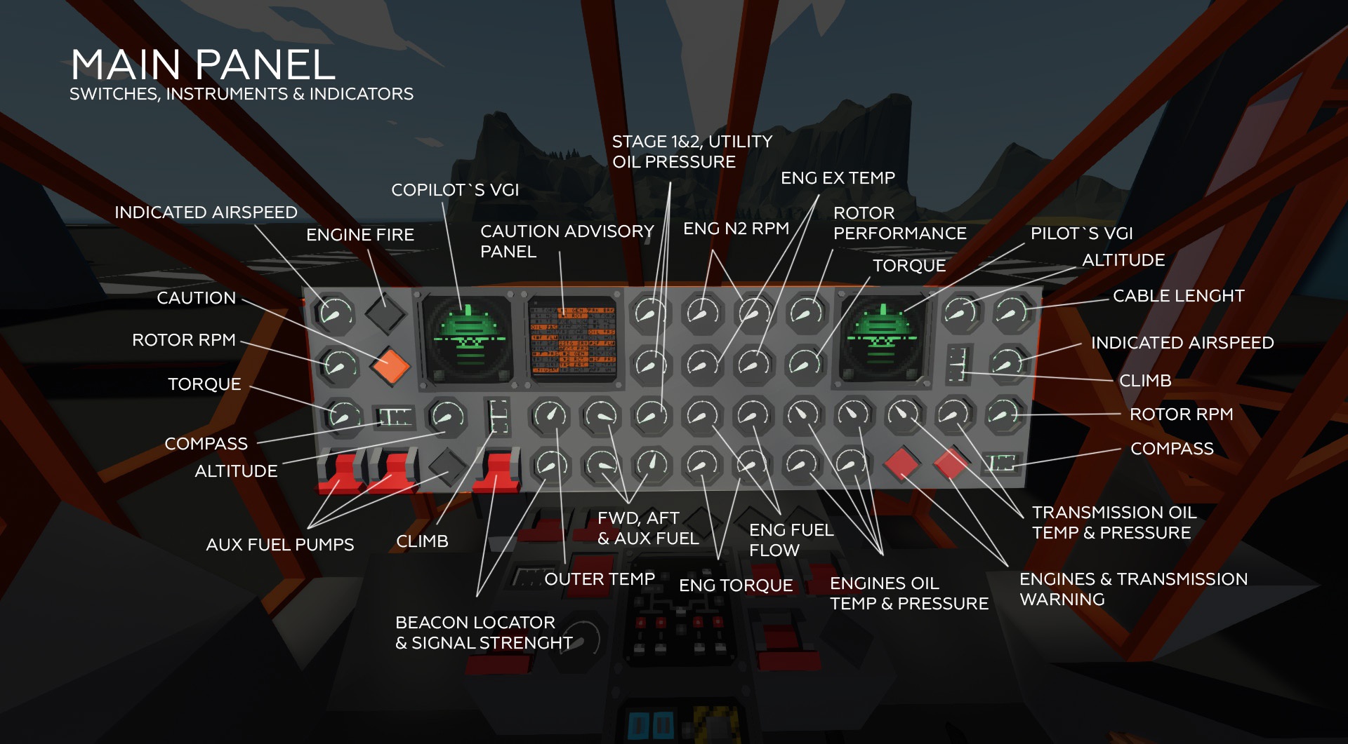
1. Indicated airspeed – shows the speed of the helicopter relative to the air, not the ground, so in a strong wind, even standing still, you can see 50 knots.
The gauge may break, the pitot tube may freeze.
2. Altiture. The gauge may break, the pitot tube may freeze.
3. Climb. The gauge may break, the pitot tube may freeze.
4. Compass – compass. The gauge may break.
5. VGI – pilot and co-pilot attitude indicator. Powered by the first and second AC bus, respectively. They can break separately, on each both axles can break.
Engines:
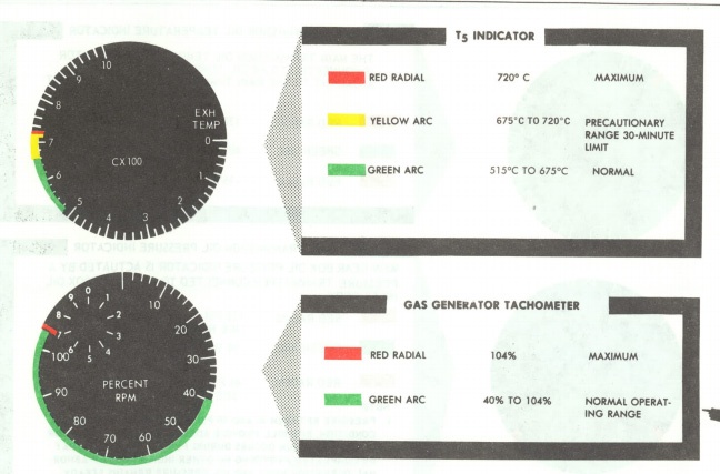
1. Eng N1 RPM – the gas generators rpm. Because engines with a free turbine, the speed of the gas generators is not directly related to the speed of the turbines, therefore the speed of the rotor will not always coincide with the speed of N1. Unfortunately, there is nowhere to place N2 tachometers onto the panel.
The nominal range is 80-104%. If 115% is exceeded, overspeed protection is triggered, the engine cuts off. To restart, you must return the N1 lever to zero position and wait for the protection to reset.
N1 tachometers are powered by their own generators and operate independently of the onboard power supply.
—————-
The rotor spin starts at 80-85% of the N1 speed. At lower rpm, the gas pressure is generally not enough to turn the rotor and the main gearbox with all the devices.
—————-
2. Eng ex temp – gas temperature at the inlet to the free turbines.
The engine limit is up to 515 C at idle speed 0-40% with a possible excess up to 525.
At nominal speed – up to 675 for a long time, up to 720 – within 10 minutes, with increased wear. Exceeding 720 leads to a quick death of the engine.
The sensors operate on thermocouples and do not depend on the onboard power supply.
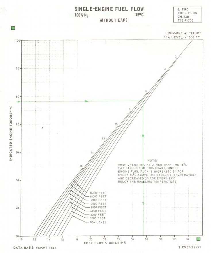
3. Eng fuel flow – The engine’s current fuel consumption in pounds per hour. They are powered respectively from the first and second AC buses.

4. Eng torque – engine torque. They are powered respectively from the first and second AC buses.
The limit is up to 82% for a long time, up to 100% within half an hour. Exceeding up to 116% is allowed for 10 seconds, further exceeding the torque or time leads to breakdown.
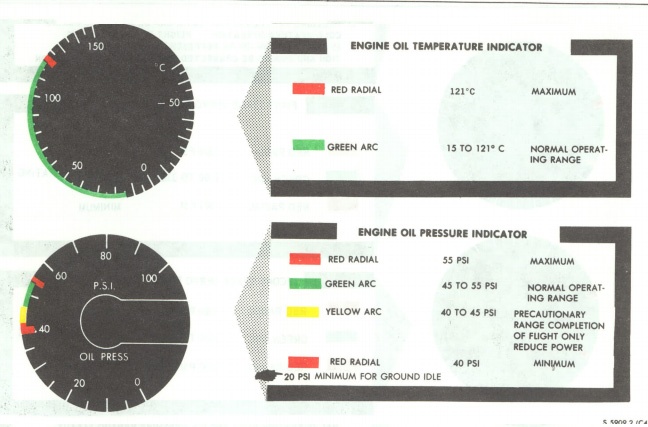
5. Engines oil temp & pressure – engines oil pressure and temperature. They are powered respectively from the first and second AC buses.
The working pressure range is 40 to 55 PSI.
Pressure depends on oil temperature, engine speed, engine wear, amount of oil left. Operating outside the permitted limits leads to wear and damage to the engines.
Temperature – up to 121 C. Exceeding it causes oil leakage, increased wear, and may result in engine fire.
Transmission:
1. Torque – torque on the input shaft of the main gearbox. Powered by the first AC bus.
The limit is 68% for a long-term, 82% is a half-hour limit. Exceeding up to 90% is allowed for no more than 10 seconds. Exceeding 90% is highly likely to cause damage to the transmission.
2. Rotor RPM – rotor speed. Powered by its own generator.
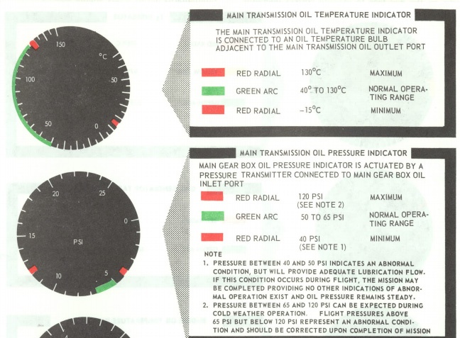
3. Transmission oil temp & pressure. Powered by the first AC bus.
The working pressure range is from 50 to 65 PSI.
Pressure depends on oil temperature, transmission pump speed, wear rate, oil quantity. Operation outside the permissible limits will result in wear and tear.
Temperature – up to 130 C. Exceeding it causes oil leakage and increased wear.
4. Rotor perfomance – Indicates what % of the available rotor lifting capability is used. In fact, it is directly related to the angle of attack of the blades.
The optimal range is 85-97%. A value below indicates inefficient rotor operation, likely overspeed and, as a result, control problems. Using 100% lift means that the powertrain does not deliver enough power to maintain the desired flight condition and can lead to uncontrollable descent and control problems.
Direct-acting device, independent of the on-board network.
Emergency lamps:
1. Engine fire – lights up when any engine is on fire.
2. Engines & transmission warning – lights up when reaching dangerous engine or transmission limits.
3. Caution – lights up when any serious or minor problem appears, duplicates the Caution advisory panel.
Hydraulics:
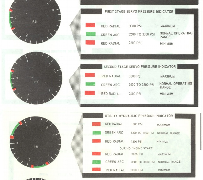
1. Stage 1 & 2, utility oil pressure – pressure in hydraulic systems. Stage 1 and Utility gauges are powered by the first AC bus, Stage 2 gauge by the second.
System pressure are dependent on temperature and oil level. Falling below 80% level is undesirable.
Fuel:
1. Fwd, aft & aux fuel – the remaining fuel in the front, rear and auxiliary tanks in pounds. Combined power supply from AC buses. The warning lamp on the Caution advisory panel is triggered by the readings of the same level sensors, therefore, if the sensors fail or not powered, there may be a false warning. The emergency lamps on the fuel control panel have their own sensors, very reliable.
2. Aux fuel pumps – control of auxiliary fuel pumps. Pump 1 pumps fuel from the auxiliary tank to the front, pump 2 to the rear. The instruction assumes priority use of fuel from the auxiliary tank.
The control lamp lights up if at least one pump is running. If the lamp does not light when the switch is turned on means the pump is not working. Breakdown of both control relays and the pumps themselves is possible.
Auxiliary devices:
Cable lenght – Shows the length of the cable unwind in feet. Doesn’t break.
Beacon locator & signal strenght – control the beacon detector. The closer the beacon, the greater the signal strength. A value> 300 usually means that even a small target can be seen without binoculars. Doesn’t break.
Caution advisory panel
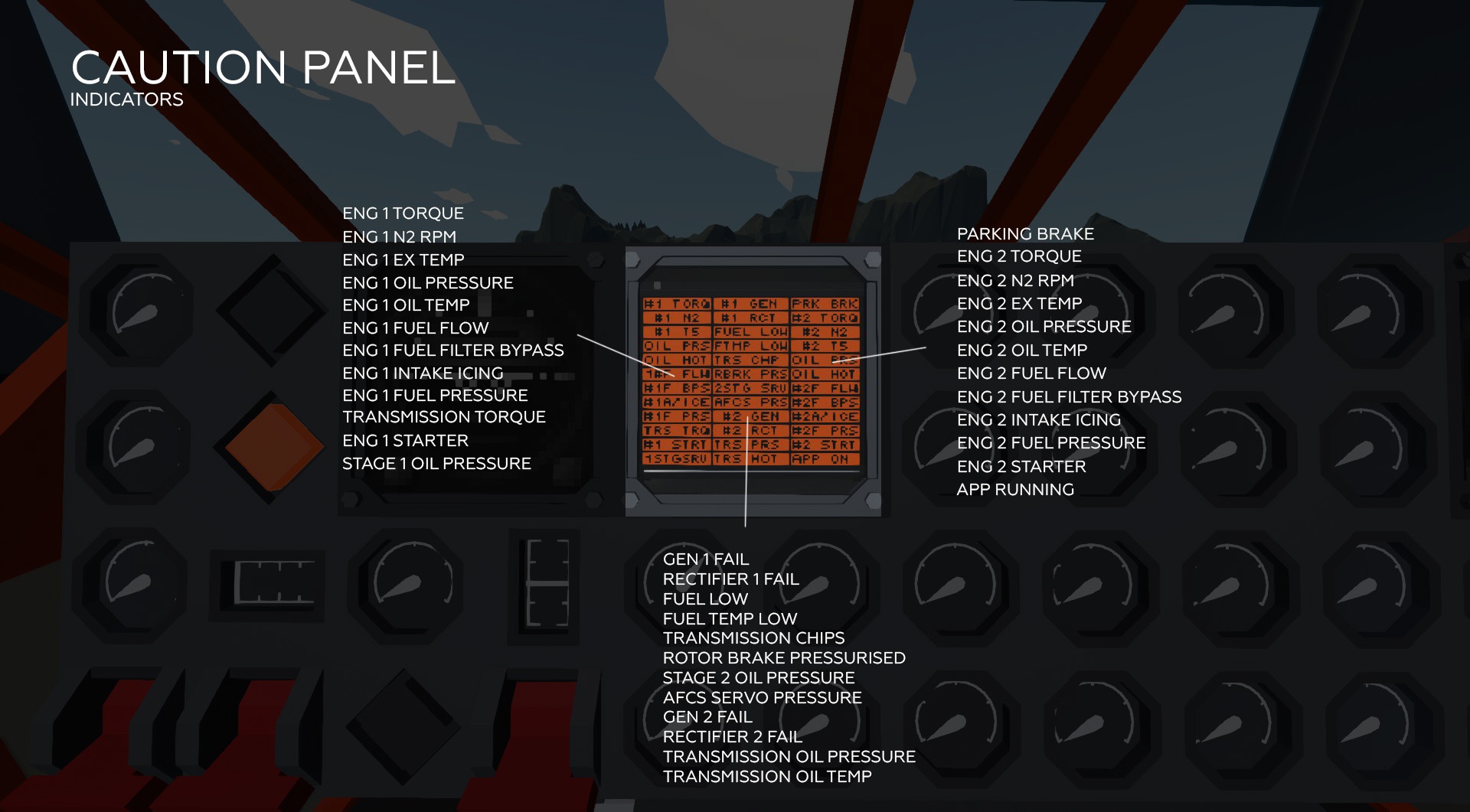
First and foremost, pressing the panel disables the alarm. When the signal is turned off, a red light is on in the corner of the panel.
Left column:
Eng 1 torque – exceeding 82% of the first engine torque. Pay attention to the engine operating mode. The sound signal is triggered when 100% torque is exceeded.
Eng 1 N2 RPM – exceeding 104% of N2 rpm. The buzzer sounds. It is necessary to reduce the speed.
Eng 1 ex temp – excess of 678 C at the turbine inlet. The sound signal is triggered when the 688 C moment is exceeded. Pay attention to the engine operating mode.
Eng 1 oil pressure – oil pressure below 30 PSI. If it lights up in operating modes, you must immediately turn off the engine. The audible signal is triggered when the pressure drops at rpm> 50%.
——————-
Attention! Oil pressure at 40% rpm must be at least 20 PSI, i.e. while in idle, warning lights on situation is normal.
——————-
Eng 1 oil temp – the oil temperature exceeds 117 C. The sound signal is triggered. Pay attention to the engine operating mode.
Eng 1 fuel flow – Fuel flow below 500 lb / hr. Rpm below idle or flame out in the engine. The buzzer sounds.
Eng 1 fuel filter bypass – the fuel filter bypass valve is open.
Eng 1 intake icing – the temperature of the intake cone is below +4.4 C.
Eng 1 fuel pressure – low fuel pressure. It is necessary to check the functioning of the main and booster pumps, and the temperature of the fuel for filter freezing.
Transmisson torque – excess 82% torque at the transmission input shaft. It is necessary to pay attention to the flight mode.
Eng 1 starter – engine starter is on.
Stage 1 oil pressure – The pressure in the stage 1 hydraulic system is less than 2000 PSI.
Middle column:
Gen 1 fail – generator # 1 failure. Monitor the voltage of the AC buses.
Rectifier 1 fail – rectifier # 1 failure. Monitor the DC bus voltage.
Fuel low – Front or rear fuel remaining less than 500 lbs.
Fuel temp low – the fuel temperature is below +0.6 C.
Transmission chips – metal chips in transmission oil. Indicates a poor condition of the transmission, or intense wear due to overload, overheating or low oil pressure.
Rotor brake pressurised – the rotary brake is on, braking.
Stage 2 oil pressure – the pressure in the stage 2 hydraulic system is less than 2000 PSI.
AFCS servo pressure – the pressure in the AFCS system is less than 2000 PSI.
Gen 2 fail – generator # 2 failure. Monitor the voltage of the AC buses.
Rectifier 2 fail – rectifier # 2 failure. Monitor the DC bus voltage.
Transmission oil pressure – oil pressure below 17 PSI. If it lights up in operating modes, you must immediately look for a landing site. The beep is triggered.
Transmission oil temp – the oil temperature in the transmission is more than 121 C. It is necessary to monitor the flight mode.
Right column:
Parking brake – the parking brake is on.
—————
Eng 2 torque
Eng 2 N2 RPM
Eng 2 ex temp
Eng 2 oil pressure
Eng 2 oil temp
Eng 2 fuel flow
Eng 2 fuel filter bypass
Eng 2 intake icing
Eng 2 fuel pressure
Eng 2 starter
^^^^^^^^^^^^
similar to the first engine
APP running – APU in nominal mode.
Overhead panel
Electrics: [/ b]
Batt volts – main battery voltage. Normally up to 28 volts.
DC bus volts – DC bus voltage (direct current). Normally 28 volts. Powered by battery or two rectifiers.
AC 1 & 2 bus volts – voltage of AC buses 1 and 2 (alternating current). Normally 115 volts. Powered by generators. The first AC bus can also be powered by an inverter and an airfield power supply via an external power relay.
The flow between the buses is carried out using a monitor relay, which allows maintaining the voltage on the bus with a failed source. The monitor relay may fail, no special indication is provided.
APU: [/ b]
APP master – general switch of the APU.
APP starter – starter. Powered by a hydraulic accumulator. To start, hold ~ 2 sec. May break or burn from repeated startup attempts.
APP ex temp – temperature of gases at the turbine inlet.
APP RPM% – The normal is 95-98%.
APP fire – fire due to oil leak, fuel, malfunction. When APU is not running, light should be on.
APP oil pressure – low oil pressure. Indication in the nominal mode means a malfunction, must turn off the APU ASAP.
APP overspeed – exceeding 100% rpm. Normal situation, the limit is 10 minutes. When APU is not running, light should be on.
APP hydroacc pressure – pressure in the hydraulic accumulator of the APU hydraulic starter. Charged by auxiliary hydraulic system. Working pressure 3000-3500 PSI.
Engines controls: [/ b]
Eng 1 & 2 N1 lever – gas generators speed control. Startup ~17-20 , idle 40, nominal mode from 85 to 105, depending on the weather and helicopter load.
Engines starters – enable engine starters. The starters are hydraulic, powered by an auxiliary hydraulic system. In the engine start mode, the valves in the hydraulic pump are switched and the pressure rises to 3300-3800 PSI.
Starters overheat and may break after several start attempts in a row. The operation of starters for more than 30 seconds without interruption is prohibited by the instruction.
The start is interrupted by closing the shutoff levers or by setting the N1 levers to 0.
Eng 1 & 2 shutoff levers are the main fuel valves of the engines. Doesn`t break.
In many cases, the engine fire extinguishes itself after a while when the fuel supply is turned off.
Engines fire – fire indicators of the first or second engine.
Engines overspeed – indicators of activation of overspeed protection of the first or second engine. The protection shuts down the engine if 117% N1 is exceeded. To restart, you need to return the N1 lever to 0 and wait until the protection turns off.
Lighting: [/ b]
All lighting elements can break.
Instruments – instrument lighting.
Cockpit – cockpit lighting.
Landing – landing lights.
Position – navigation lights.
Strobe – flashing lights.
Cargo – cargo lighting.
Auxiliary equipment: [/ b]
Works only when auxiliary power is on (power panel -> Pod power)
Water tank level – water level in the tank. Technically, 10 tons of water can fit into the tank. But this version of the helicopter cannot lift 10 in normal mode, so the tank capacity is reduced to about 6 tons.
Water drop doors – water drop.
Water cannon – water cannon. The tilt of the water cannon is controlled from the co-pilot’s seat.
Snorkel engage – lowering the snorkel to draw water from sea or rivers.
Fuse panel
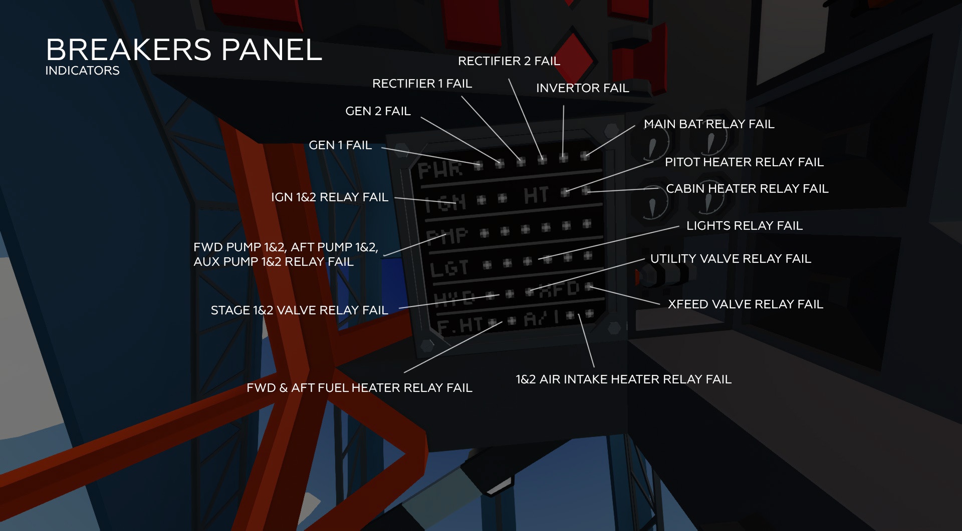
The fuse panel only shows electrical faults.
All electrical problems are repaired by a button under the upper hood of the cabin.
PWR segment, fault from left to right:
Generator 1
Generator 2
Rectifier 1
Rectifier 2
Inverter
Main battery relay
IGN:
First engine ignition module relay
Second engine ignition module relay
HT:
Pitot tube heating relay
Cabin heater relay
PMP:
Fwd group pump 1 relay
Fwd group pump 2 relay
Aft group pump 1 relay
Aft group pump 2 relay
Auxiliary group pump 1 relay
Auxiliary group pump 2 relay
The absence of an electrical fault does not guarantee the absence of fault of the pumps themselves!
LGT:
Cockpit lighting
Navigation lights
Landing lights
Instrument lighting
Cargo lighting
Strobe lights
HYD:
Stage 1 valve relay 1
Stage 2 valve relay 2
Utility hydraulic system valve relay
The absence of an electrical fault does not guarantee the absence of fault of the hydraulic systems!
XFD:
Fuel crossfeed valve relay.
F.HT:
First engine fuel heating valve relay
Second engine fuel heating valve relay
A / I:
First engine intake cone heating valve relay
Second engine intake cone heating valve relay
External control and maintenance panels
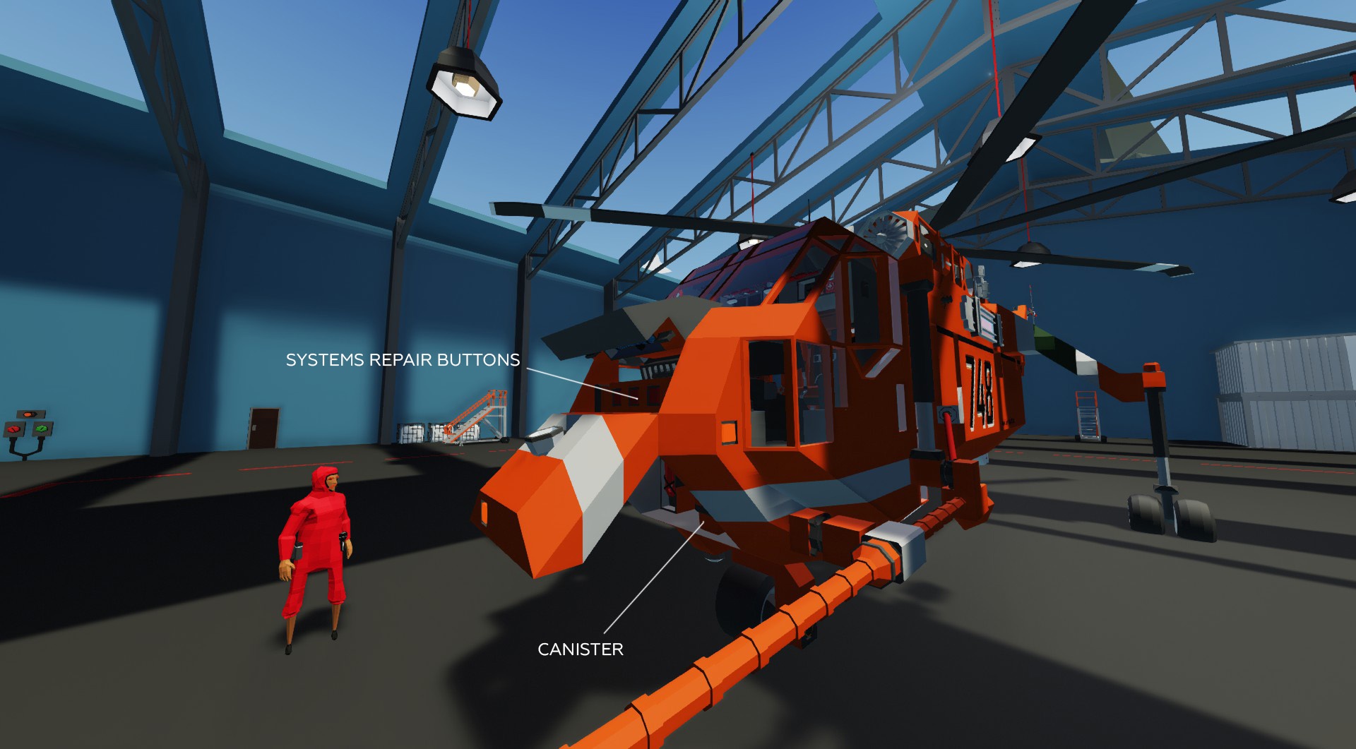
Under the upper hood: [/ b]
– Electrical repair (all relays from fuse panel, monitor relay)
– Instruments repair
– Lighting repair
– Radio repair
Additionally, in the cockpit, under the pilot’s seat, there is a button for the repair of the VGI.
Under the lower hood: [/ b]
– Canister for filling with oil of all devices, hydraulic systems and fire extinguishers
– Toggle heading control layout from A / D to left / right. For me personally, it is more convenient to be able to control the helicopter with one hand, but I know that there are adepts of the traditional layout here.
– Chicken switch – removes faults, fires, oil consumption, wear. However, if you really want to, then the powertrain can still be ditched, just the threshold of it`s durability is shifted far beyond the boundaries of realism.
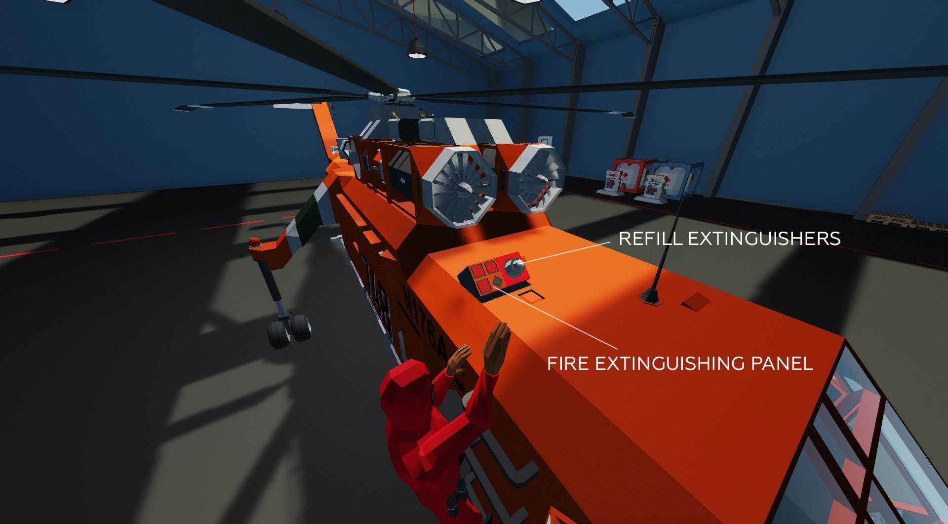
Firefighting: [/ b]
In fact, there is no fire extinguishing system on this helicopter. Extinguishing is carried out with hand-held fire extinguishers. Due to the impossibility of simulating a real fire, the extinguishing process is simulated through this panel. To extinguish something, we need to go up to the roof to the engines and pretend that we are extinguishing something. The buttons are signed, the light is on in case of fire.
Attention! There are only two extinguishing charges for each engine. Refueling the system is considered fair only at the base for role-play reasons. Refueling is carried out by connecting the canister
.
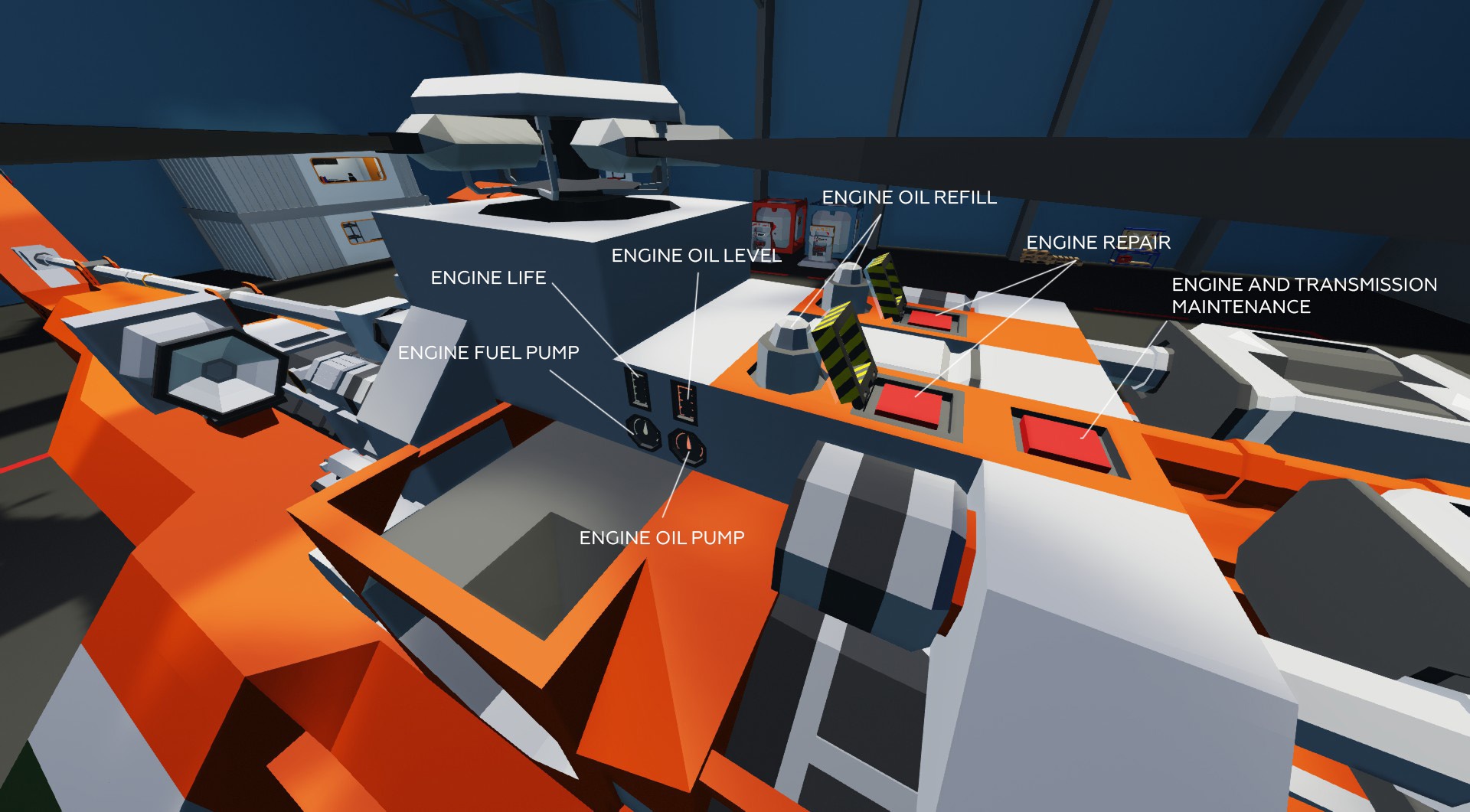
Engines: [/ b]
– Oil level indicator 0-100%.
– Engine life indicator 0-100%.
– Indicator of operation of the main fuel pump of the engine – if the pump is broken, the needle will not spin, and the engine will lose power.
– Oil pump operation indicator – if the pump is broken, the needle will not spin, and the engine will lose oil and behave badly.
– Engine repair button – active only when the engine speed is less than 5%. Repair occurs only when turned on, leaving it turned on is useless, this will not save you from breakdowns.
– Button for maintenance of transmission and engines. Sit and hold to restore the condition of the units. Works much faster if engine or transmission was not killed dead.
– Ports for engine oil filling. Use a canister.
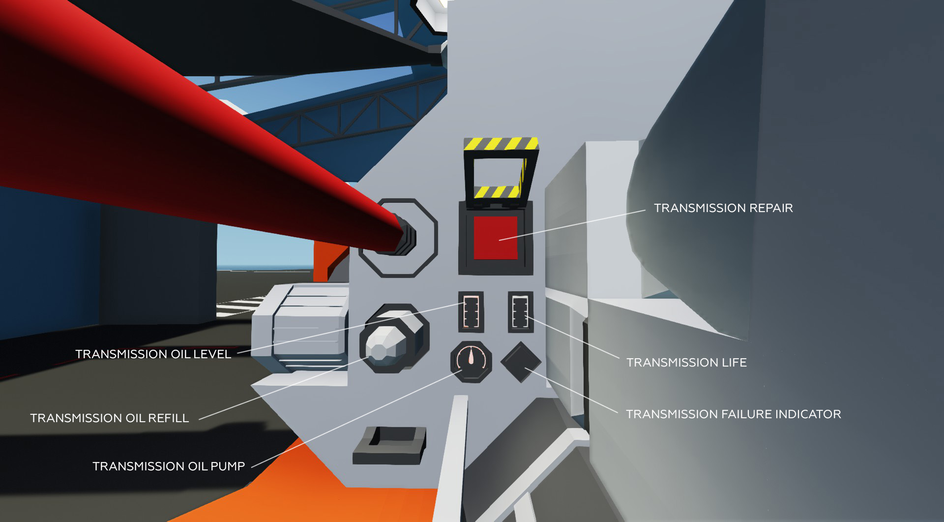
Transmission: [/ b]
– Oil level indicator 0-100%.
– Transmission life indicator 0-100%.
– Oil pump operation indicator – if the pump is broken, the needle will not spin, and the transmission will lose oil and pressure, which will eventually lead to a fall.
– Repair button. Active only when the transmission is almost completely stopped.
Attention! Stopping the rotation of the rotor does not mean stopping the transmission. The auxiliary unit of transmission can continue to rotate while APU is running. To repair the transmission, the helicopter must be completely shut down.
– Oil filling port.
– On the right side of the helicopter there is a fuel pumps repair button.
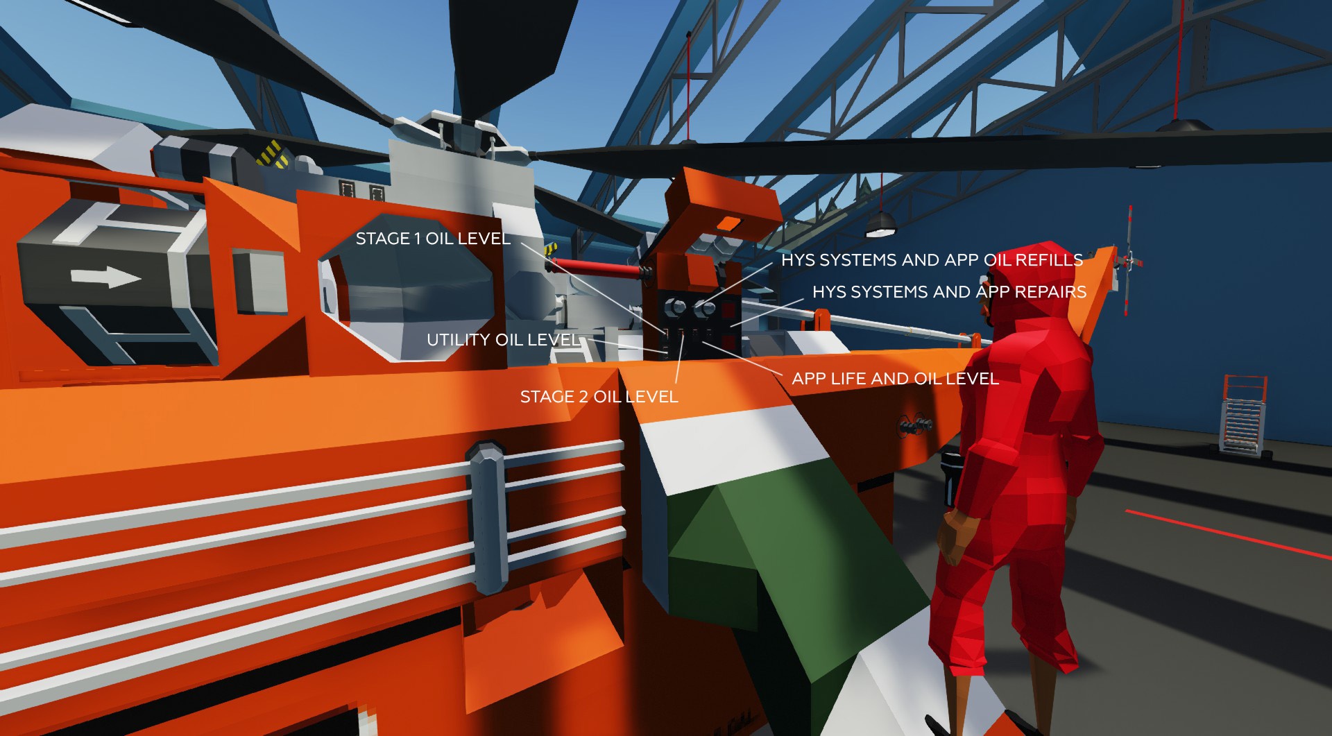
Hydraulic systems and APU: [/ b]
– Oil level in hydraulic systems
– Indicator of mechanical failure of hydraulic systems
– Oil level in the APU
– APU life
– Buttons for repairing hydraulic systems and APU.
– Oil filling ports, left for hydraulic systems, right for APU.
Some possible malfunctions, symptoms and solutions
List of major faults, from minor to major. Many minor faults are not mentioned.
———————-
– Signs: gauge needles twitch
– Possible malfunction: breakdown of instruments, freezing of the pitot tube, oil leakage from engines or transmissions, failure or low pressure AFCS
– Action: check the fuses, check the emergency lamps, the temperature of the powertrain, the stability of the operation and the parameters of the engines, the probability of icing, the condition of the hydraulic systems and the operation of the AFCS.
If everything is ok, the diagnosis is a gauge breakdown.
———————-
– Signs: external or internal lighting flashing
– Possible malfunction: the corresponding relay is faulty, low voltage of the on-board network
– Action: check the emergency lamps of the generators / rectifiers, check the mains voltage, check the fuses.
Determine the fault by the state of the fuses.
———————-
– Signs: VGI twitches or does not work
– Possible malfunction: VGI broke, power was lost
– Actions: use the co-pilot`s VGI, check the power
———————-
– Signs: radio does not work
– Possible malfunction: radio breakdown, power loss
– Actions: fly in silence, check the power
———————-
– Signs: a red light on the fuel panel is on
– Possible malfunction: pump relay failure, pump failure, out of fuel
– Actions: check fuses, check fuel level, turn on xfeed, keep flying
———————-
– Signs: the heater does not work
– Possible malfunction: relay breakdown
– Actions: check fuses, freeze
———————-
– Symptoms: no DC bus power supply
– Possible malfunction: the main battery relay is turned off or faulty, the rectifiers are turned off or faulty
– Actions: check the fuses, turn on the battery, check the emergency lamps of the rectifiers
———————-
– Signs: there is no power on one of the AC buses, some devices do not work
– Possible malfunction: generator breakdown, inverter breakdown, monitor relay breakdown
– Action: check fuses, check generator emergency lamps
———————-
– Symptoms: no power on both AC buses
– Possible malfunction: APU or engine are not started + inverter is off, both generators are malfunctioning
– Actions: check everything
———————
– Signs: everything is blinking, all gauges are twitching OR the battery is not charging
– Possible malfunction: breakdown of the main battery relay
– Actions: check the fuses, disconnect the battery and fly using the generators only
———————-
– Symptoms: Engines won’t start
– Possible malfunction: the ignition is turned off or broken, there is no fuel pressure, the main fuel pumps are faulty, the shutoff levers are closed, the N1 levers are closed, there is no pressure in the auxiliary hydraulic system
– Actions: check the ignition indication is turned on when the engine is cranking, check the operation of the pumps, check the main pump, check the position of the levers, check the pressure in the auxiliary hydraulic system
———————-
– Signs: pressure has disappeared in one of the main hydraulic systems
– Possible malfunction: pump valve relay failure, pump failure, oil leak
– Actions: check the fuses, check the pressure in the remaining hydraulic system, if possible, land and repair
———————-
– Signs: the pressure in the auxiliary hydraulic system has disappeared
– Possible malfunction: pump valve relay failure, pump failure, oil leak
– Action: check fuses, continue flying, do not use the rotor brake, do not restart the engines until the hydraulic system is repaired
———————-
– Signs: the APP OVERSPEED light is on when the APU is operating
– Possible malfunction: not malfunction
– Actions: turn off the APU if it is not needed
———————-
– Signs: the APP OIL PRESSURE light blinks or is on when the APU is operating
– Possible malfunction: oil leak from the APU
– Actions: turn off the APU as soon as possible in order to avoid damage and fire
———————-
– Signs: APP FIRE light is on
– Possible malfunction: APU is on fire!!!
– Actions: climb on the roof of the cabin, open the fire extinguishing panel, extinguish
———————-
– Signs: twitching or inadequate readings of speed indicator, altimeter or variometer
– Possible malfunction: icing of the air pressure receiver or failure of its heater
– Actions: check the fuses, turn on the heating, if it does not work, go to visual flight
———————-
– Signs: sudden loss of engine power
– Possible malfunction: breakdown of the main pump of the engine, breakdown of both booster pumps, icing of the intake cone, freezing of fuel in the filter, poor condition of the engine after overload, out of fuel, overspeed protection active
– Actions:
1.Check the fuel pressure warning light + engine consumption + check the pump operation indicator on the engine. If the lamp is on, the flow is low, the pump does not rotate – the pump is broken. Look for an emergency landing site or fly on as it is.
2. If the "F BPS" light is on, the fuel in the filter is frozen. Turn on heating.
3. If the A / ICE light is on, the engine intake is likely to become icy. Turn on heating.
4. Check the control lamps of the booster pumps, turn on xfeed, check the fuel level. If the lamps are off and xfeed has not corrected the situation, there is fuel in tanks – the engine is badly worn out.
———————-
– Signs: the engine is unstable, the oil pressure jerks, the oil temperature rises, the ext temperature rises
– Possible malfunction: oil leak into the engine, high probability of fire
– Action: land as soon as possible, repair the leak, add oil, extinguish the engine. If it is impossible – turn off the engine and fly on one, if necessary, drop the load.
———————-
– Signs: for no apparent reason, the ext temperature and fuel consumption increase
– Possible malfunction: fuel leakage into the engine, breakage of injectors
– Action: check the drop in the fuel level in the tanks, in case of abnormal consumption – turn off the faulty engine as soon as possible. Very high risk of fire!
———————-
– Signs: unstable transmission oil pressure, rising oil temperature
– Possible malfunction: oil leak from transmission
– Action: If possible, check the breakdown indicator on the transmission and land as soon as possible.
———————-
– Signs: emergency torque, N2 or T5 warning lights, high oil temperature in engines or transmissions, rotor perfomance about 100%
– Possible malfunction: helicopter overload
– Actions: unload unnecessary items/crew
———————-
– Signs: the helicopter behaves inadequately in flight, twitches, does not maintain speed, altitude or direction, sways heavily
– Possible malfunction: overload, AFCS malfunction, low pressure in hydraulic systems
– Action: check the fuses, check the pressure in the hydraulic systems. If necessary, disable AFCS, make a manual emergency landing.
Anyone who has read this far is a fine fellow. Happy flights!
Hope you enjoy the Guide about Stormworks: Build and Rescue – S-64 Sikorsky Skycrane full manual, if you think we should add extra information or forget something, please let us know via comment below, and we will do our best to fix or update as soon as possible!
- All Stormworks: Build and Rescue Posts List


Leave a Reply