
A simple guide that shows basic Flip-Flops, how they work and how to make them.
General
“In electronics, a flip-flop or latch is a circuit that has two stable states and can be used to store state information.” Flip-flops are made of smaller components called logic gates. This guide shows how they work and how to make them in Logic World
SR latch
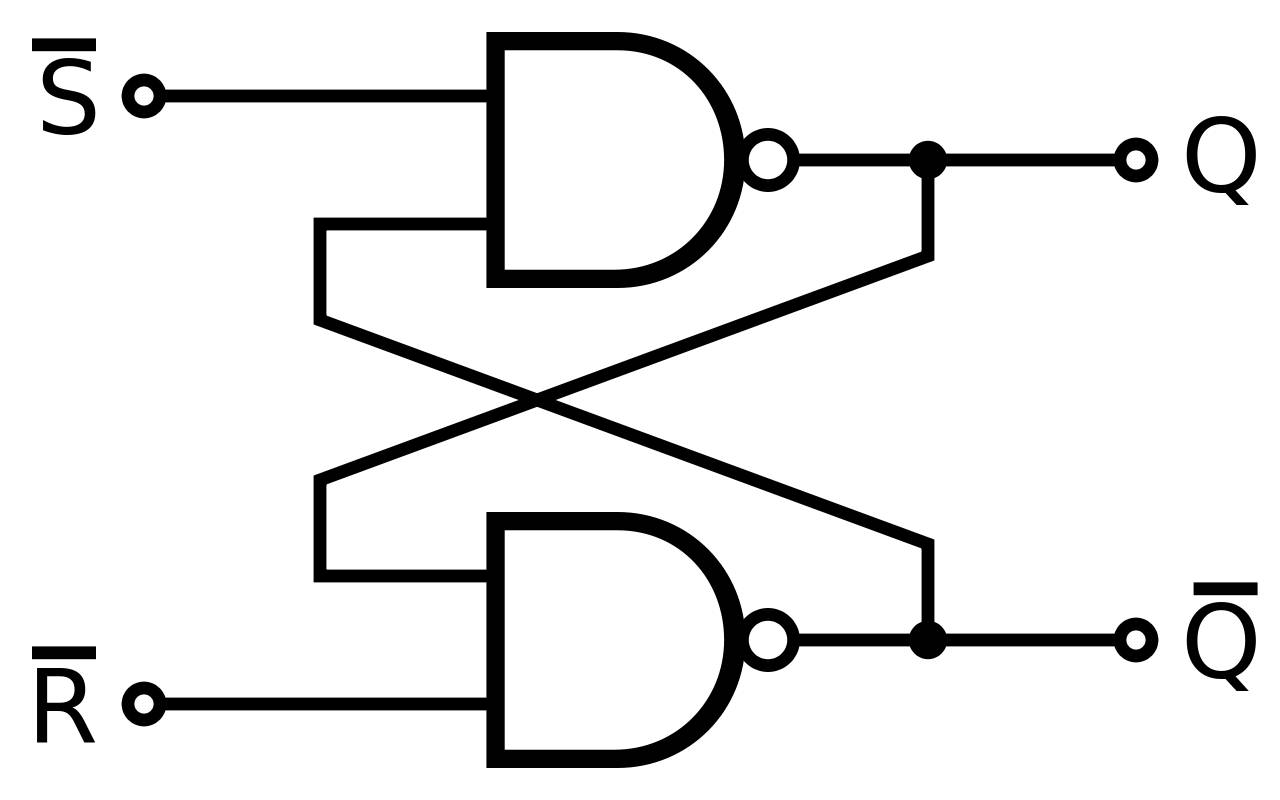
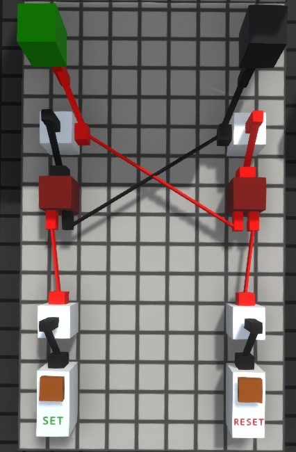
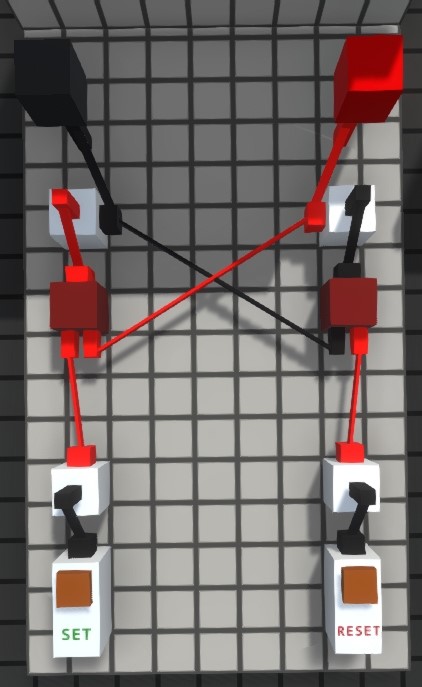
SR or Set-Reset latches are used to set the output to 1 with S input and reset to 0 with R input.
SR latches take two inputs and give one output based on input combination as following:
| S | R | Q |
|---|---|---|
| 0 | 0 | Q |
| 1 | 0 | 1 |
| 0 | 1 | 0 |
| 1 | 1 | X* |
*X – forbidden state
Diagram:
In-game:
JK latch
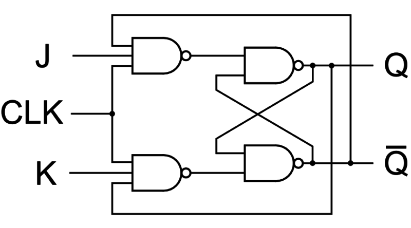
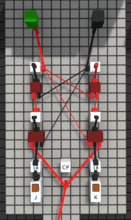
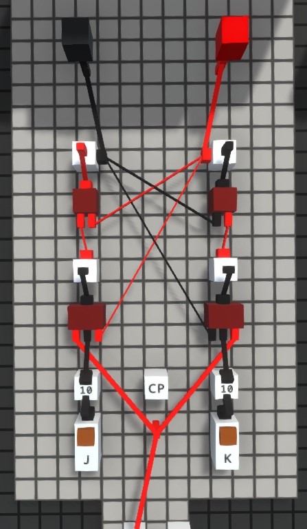
JK latches are similar in behaviour as SR latches, but instead of having the forbidden state, they have the “flip” state, which means the next output is going to be inversed current output.
JK latches also take two inputs and give one output based on input combination as following:
| J | K | Q |
|---|---|---|
| 0 | 0 | Q |
| 1 | 0 | 1 |
| 0 | 1 | 0 |
| 1 | 1 | Q’ |
Diagram:
In-game:
As seen, JK latch has an additional signal CP or CLK (Clock) which controls how often inputs affect the latch. Easiest way to make a clock is to connect output of a delayer to input of inverter and vice versa. Any node can be used as an output. Notice that frequency can be changed by editing the delayer.
T Latch
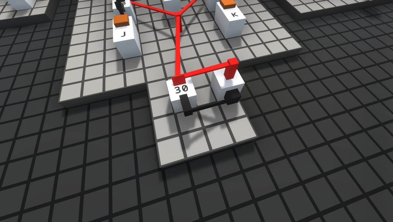
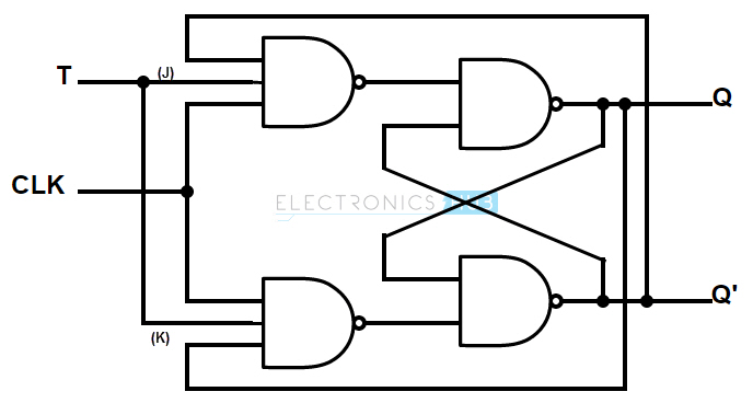
T latches have one input connected to both inputs of an JK latch so it only has the “flip” state.
T latches take one input and give one output based on input combination as following:
| T | Q |
|---|---|
| 0 | Q |
| 1 | Q’ |
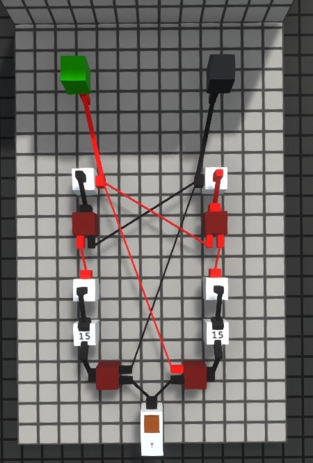
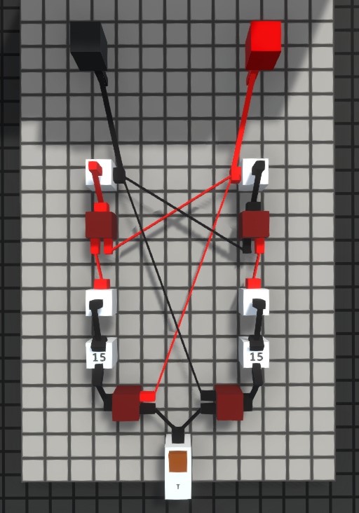
Diagram:
Notice the diagram has a clock, but I haven’t used it because I added the delayers inside the circuit.
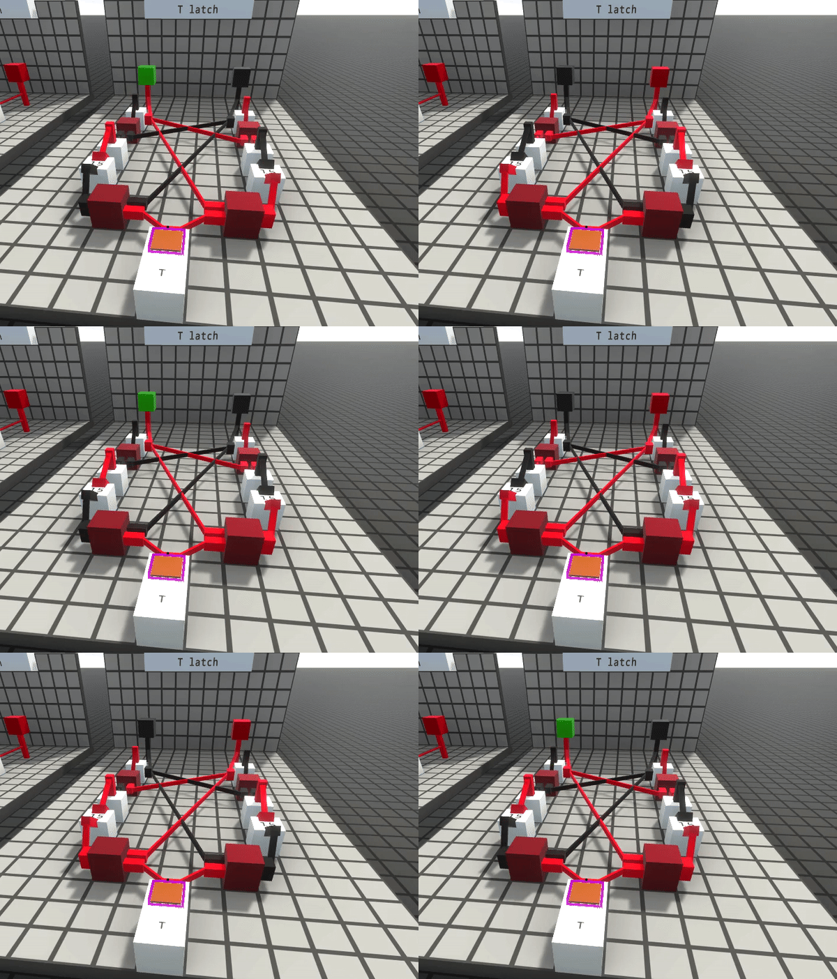
In-game:
Conclusion
That’s all I managed to do for now, I will update it when I can. This guide is not finished, I still have to make the D latch and maybe add some other things. Hope this helped at least a little bit.
Happy engineering
I hope you enjoy the Guide we share about Logic World – Basic Flip-Flops & Latches Tips; if you think we forget to add or we should add more information, please let us know via commenting below! See you soon!
- All Logic World Posts List


Leave a Reply