A simple 7 segment display with 4 bit addressing.
Introduction
This is the English translation of my guide to building a 7 segment display.
7 Segment Anzeige mit 4 Bit Adressierung – [steamcommunity.com]
Hier gehts zur Deutschen Version.
In this guide I will show you how to build a simple 7 segment display and control it with 4 bits.
The display and the address block are modular, which simplifies copying or expanding.
In addition, we are building a test station for the display.
Am Ende wird sich folgende Tabelle ergeben:
| 1 (2^0) | 2 (2^1) | 4 (2^2) | 8 (2^3) | Anzeige |
|---|---|---|---|---|
| 0 | 0 | 0 | 0 | 0 |
| 1 | 0 | 0 | 0 | 1 |
| 0 | 1 | 0 | 0 | 2 |
| 1 | 1 | 0 | 0 | 3 |
| 0 | 0 | 1 | 0 | 4 |
| 1 | 0 | 1 | 0 | 5 |
| 0 | 1 | 1 | 0 | 6 |
| 1 | 1 | 1 | 0 | 7 |
| 0 | 0 | 0 | 1 | 8 |
| 1 | 0 | 0 | 1 | 9 |
| 0 | 1 | 0 | 1 | A |
| 1 | 1 | 0 | 1 | B |
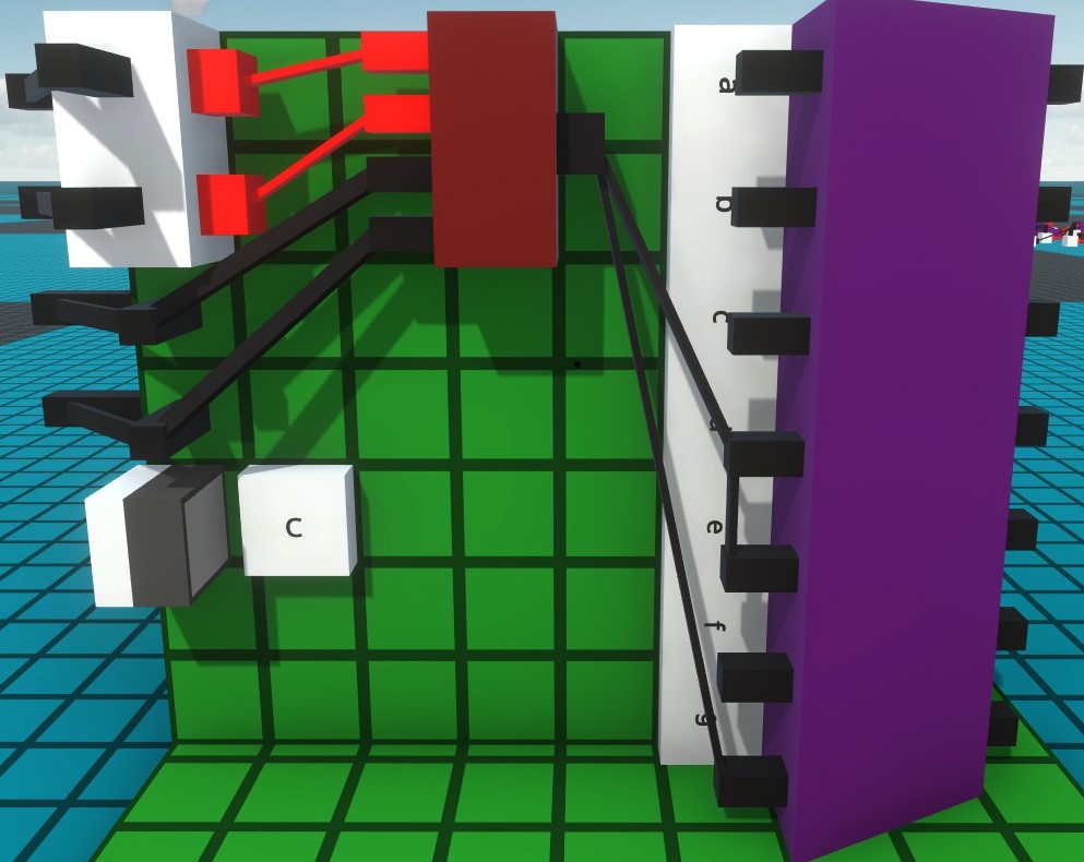
| 0 | 0 | 1 | 1 | C |
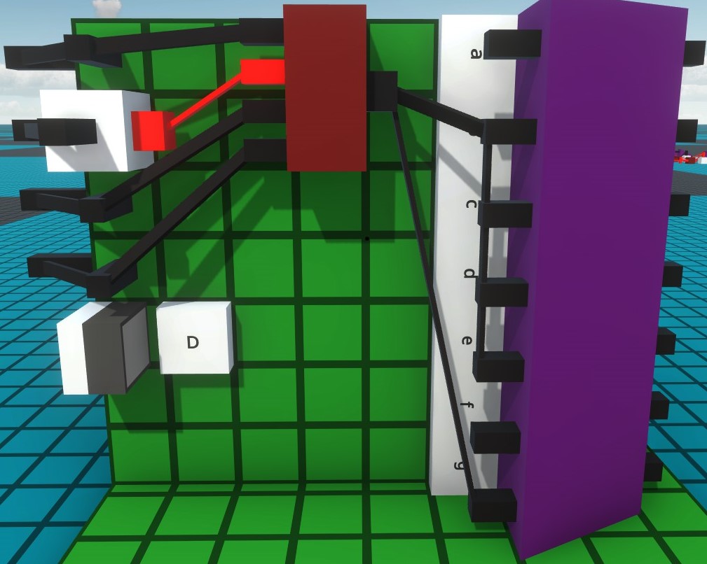
| 1 | 0 | 1 | 1 | D |
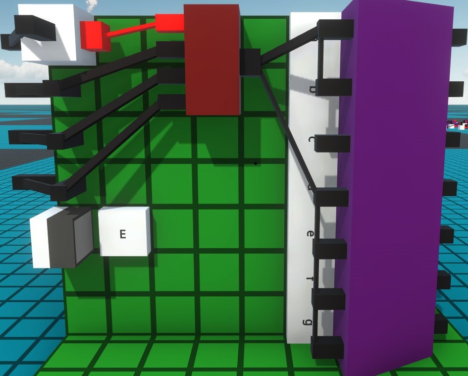
| 0 | 1 | 1 | 1 | E |
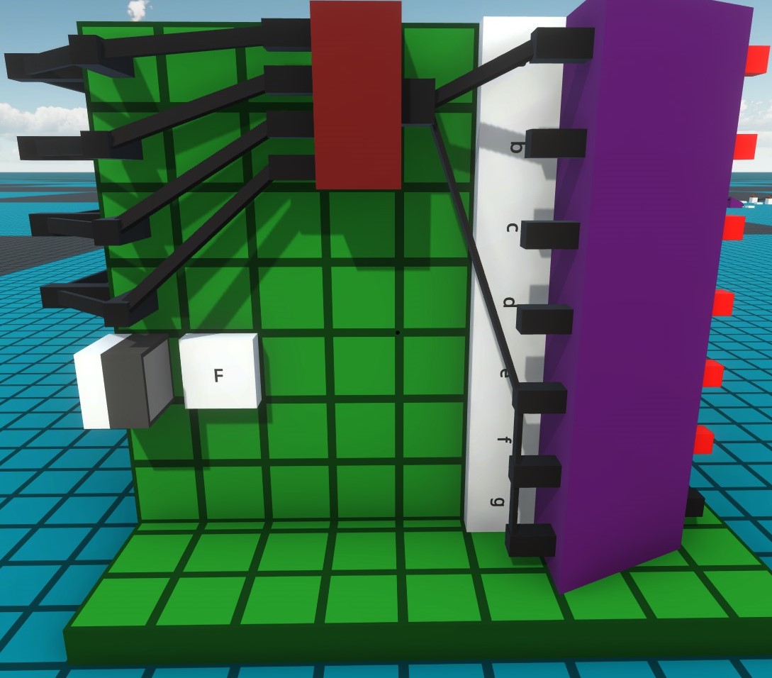
| 1 | 1 | 1 | 1 | F |
7 Segment Display
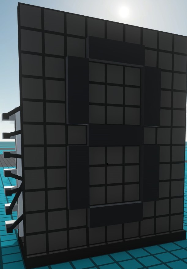
The construction of the 7 segment display is the simplest part of this project.
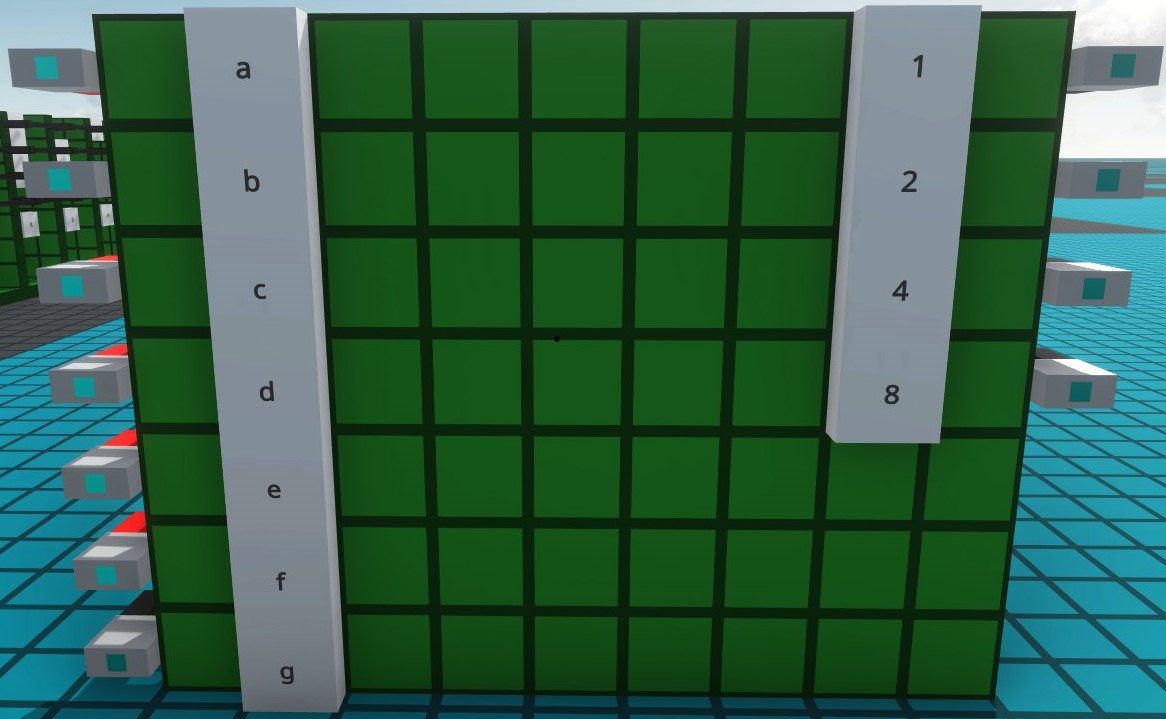
The display is built on a 9×4 board.
The actual display is embedded in a 9×11 plate.
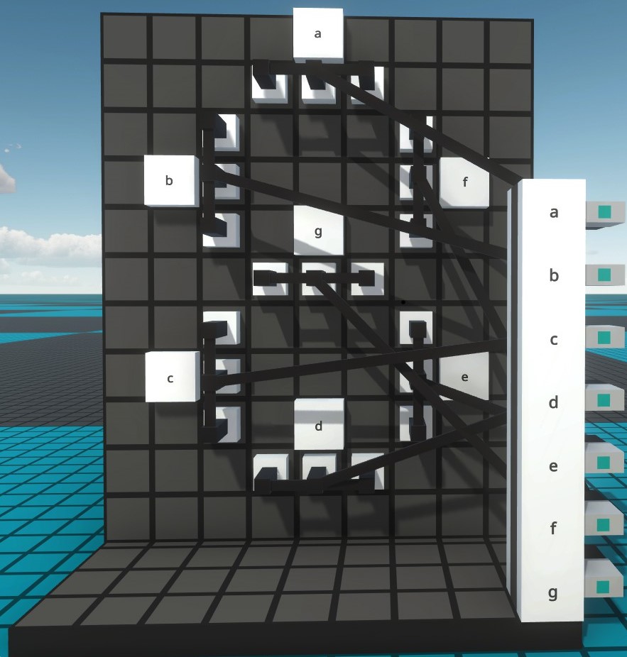
Each segment consists of 3 recessed lights.
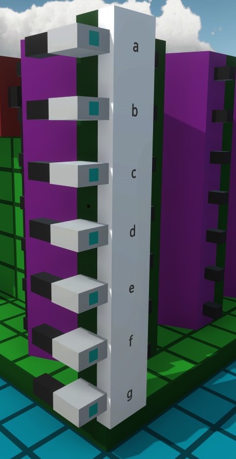
The segments are interconnected and marked with a small letter.
To keep the display modular and easy to connect I included a connector s*rip. Simply connect the plug to the corresponding letter.
That would finish the display. However, a control is still missing.
Controlling with 4 bits
The control is kept simple.
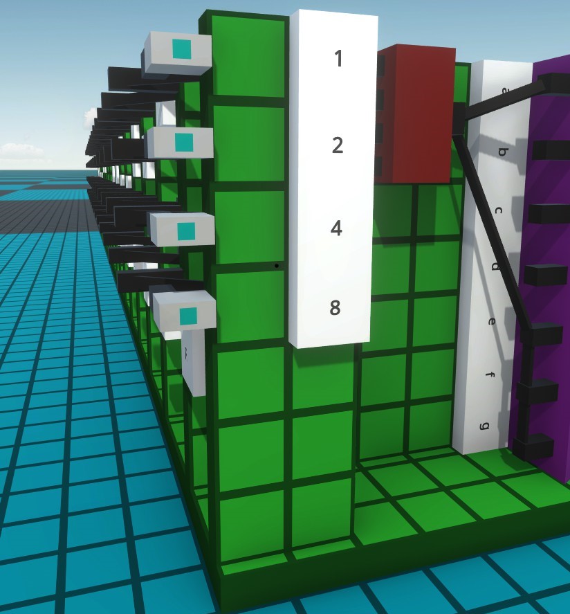
I use 4-bit addressing for the individual numbers, which means there will be an address board for each number. All will be connected at the side via a bus.
The structure gets a little bigger. If you want to use all 16 numbers, the base plate will be 9×48
If you only want to use 8 numbers, you can of course shorten them the plate to half.
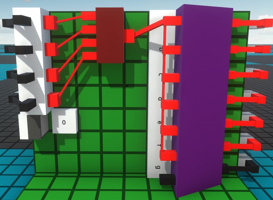
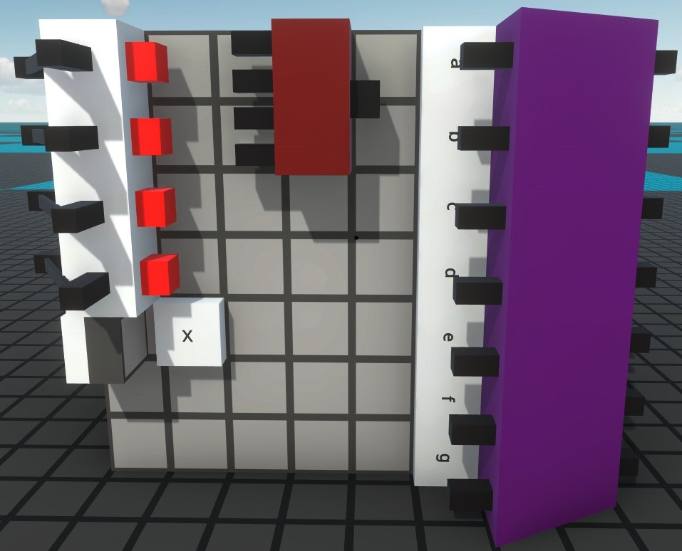
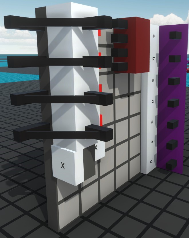
The first address board differs from the others because of the connectors on the side for the bus connection. The board is 9×7 in size.
This is the front of the address block, the 7 segment display will be docked here later.
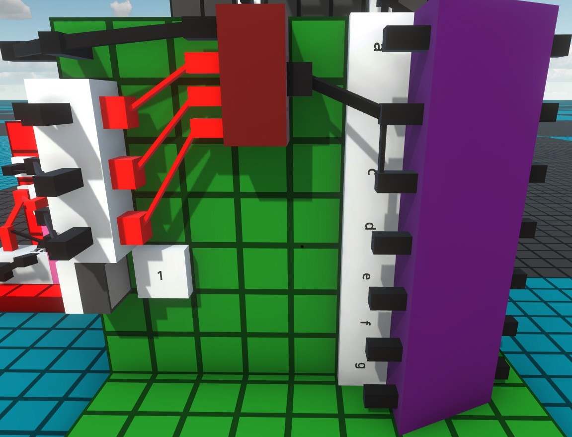
Here you can see the structure for the number 0 on the back of the circuit board.
For the later circuit boards, I recommend preparing a circuit board
The board is 8×7 in size.
If necessary, the inverters are exchanged for nodes.
The structure should be on the same site as the first board.
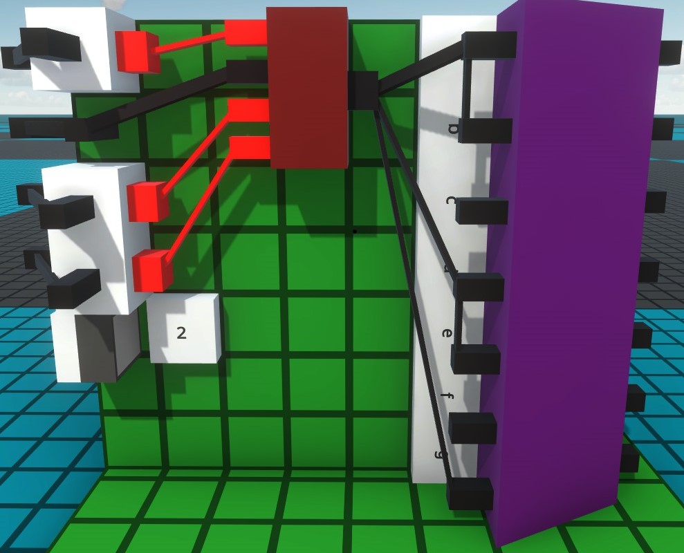
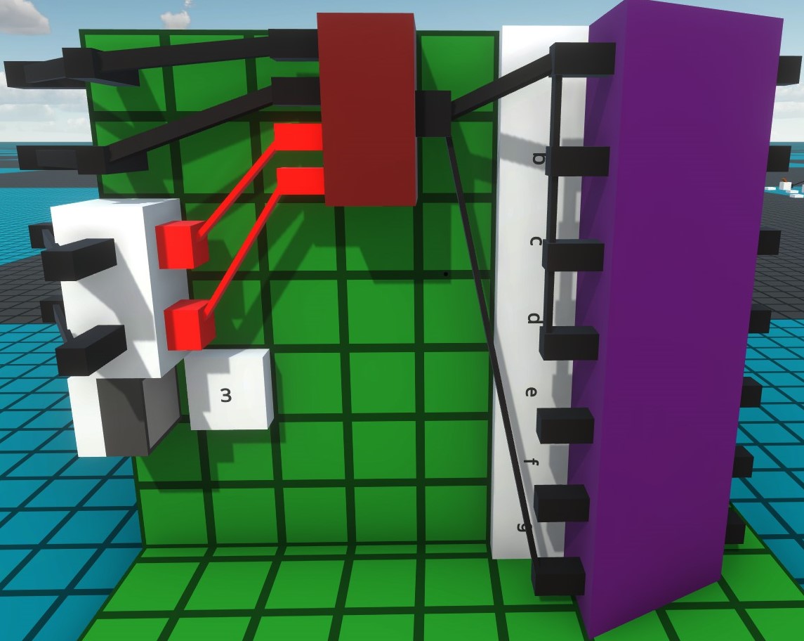
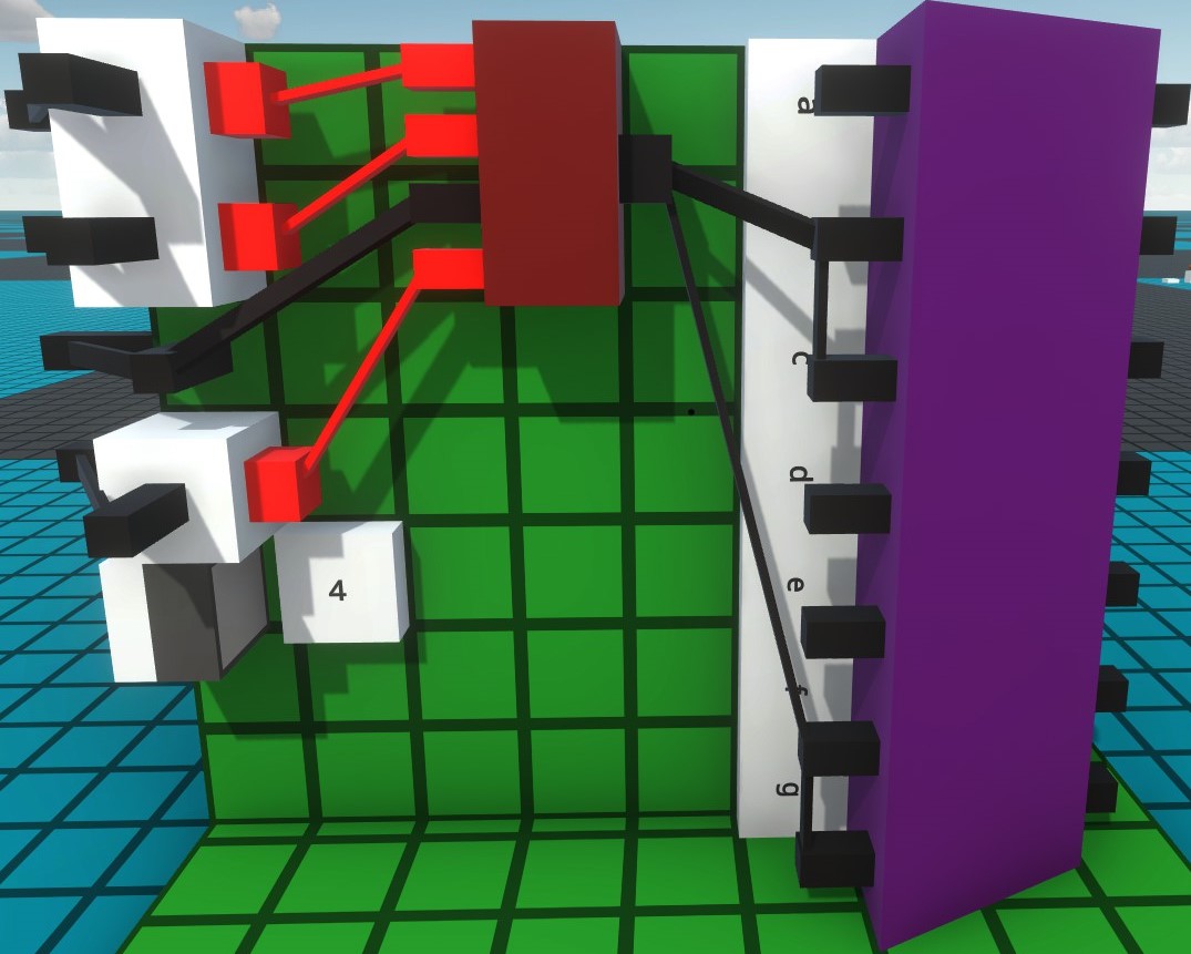
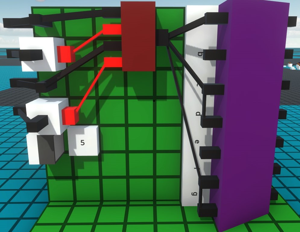
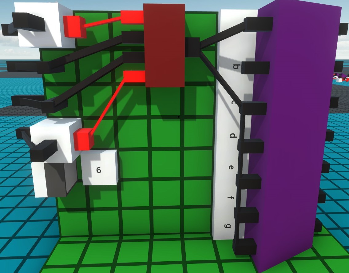
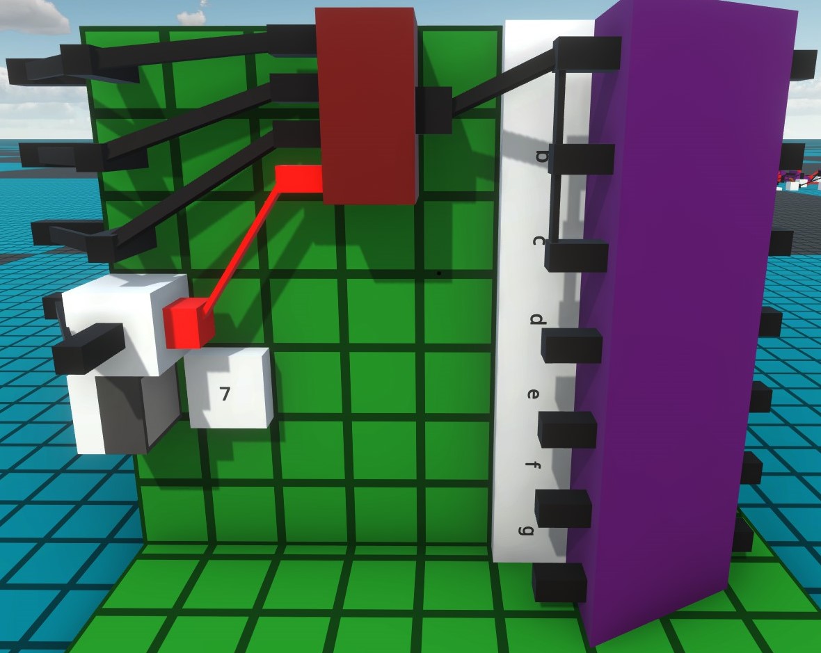
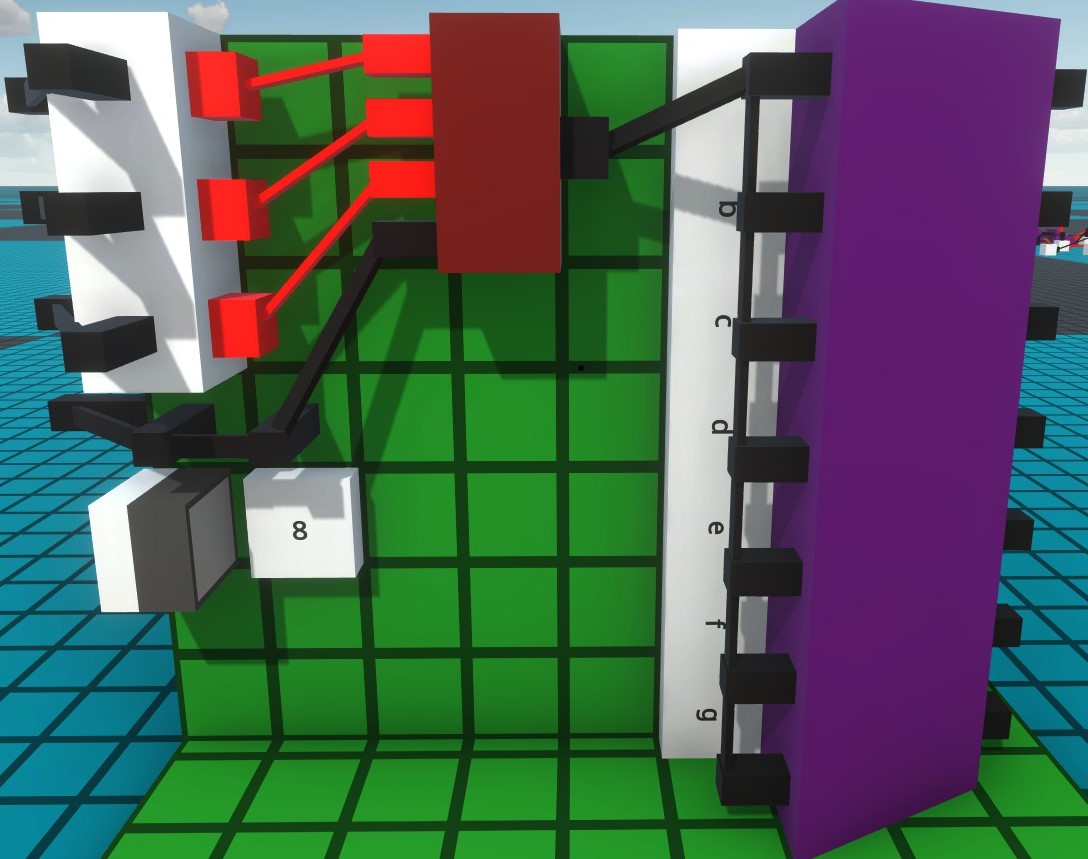
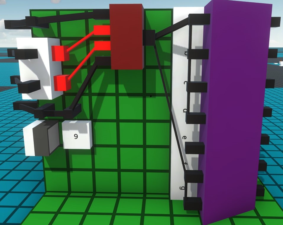
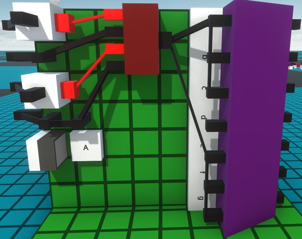
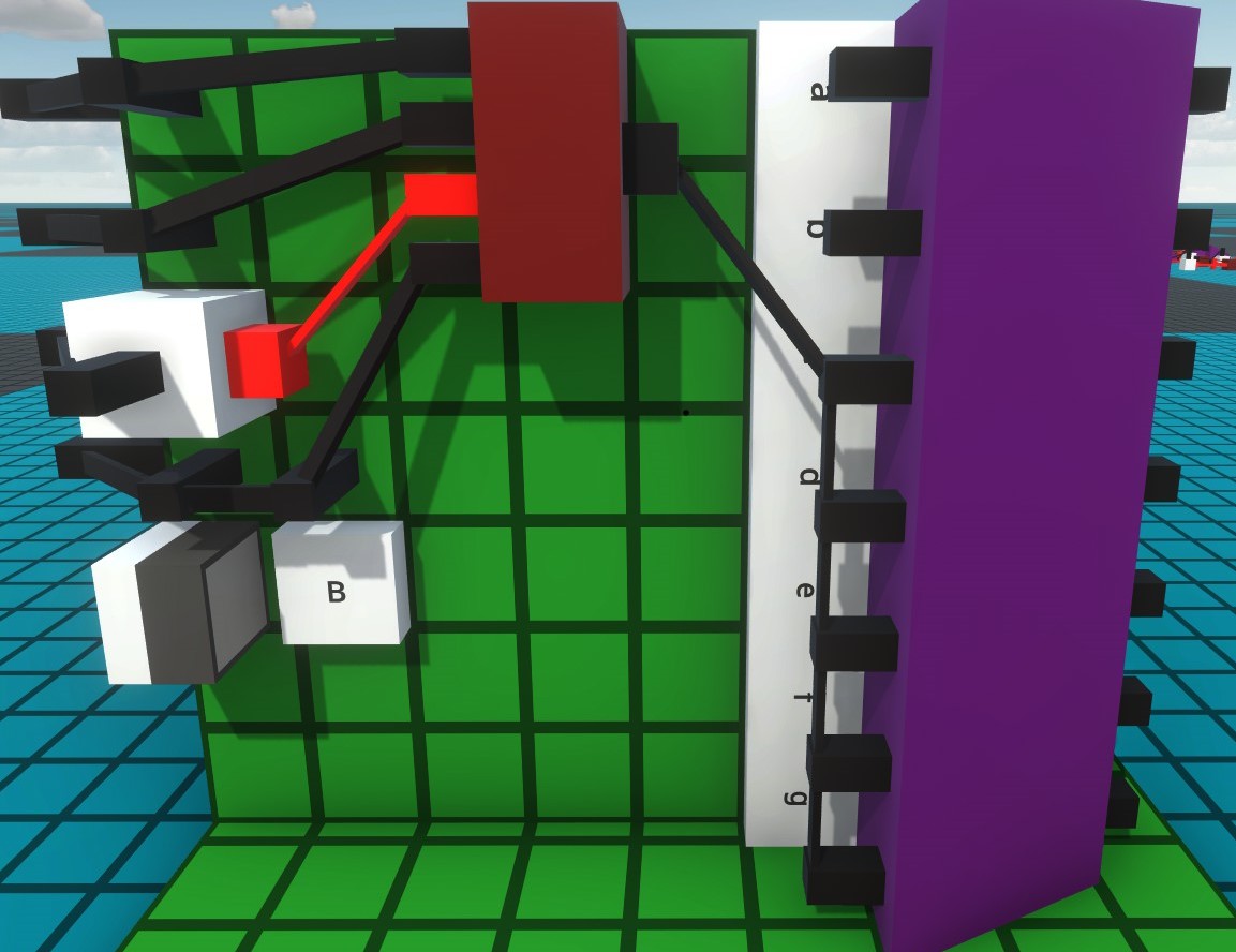
From here follows a series of pictures of the other address cards.
With that you would have all the address cards ready.
If you want, you can also mount connector strips at the back:
But this is purely optional.
All you have to do now is connect the bus lines on the sides:
With that, the address module would be finished, just place the 7 segment display on the front of circuit board 1 and you’re done.
Teststation
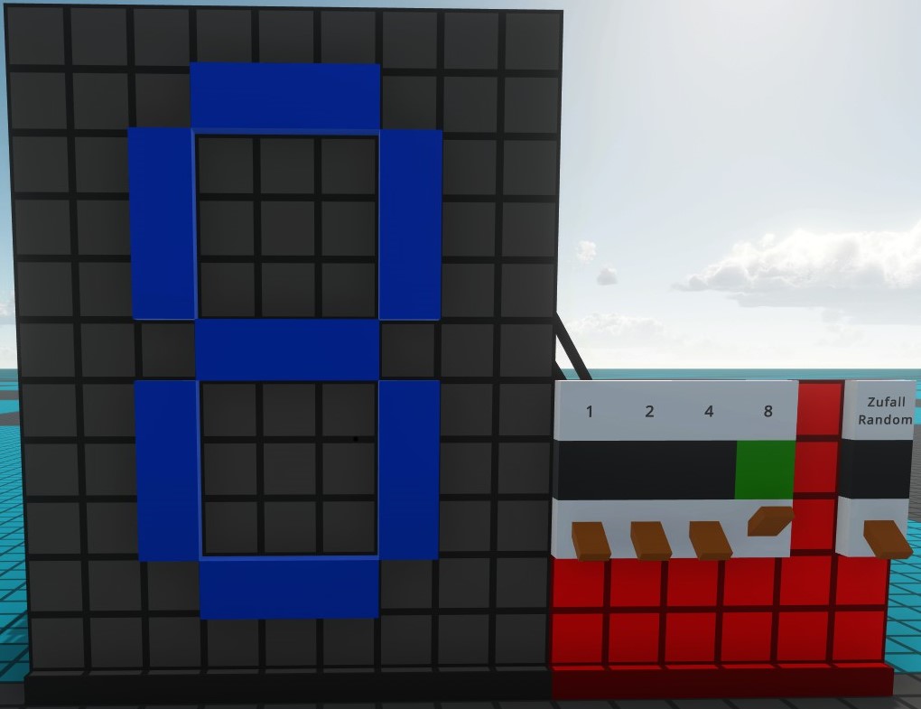
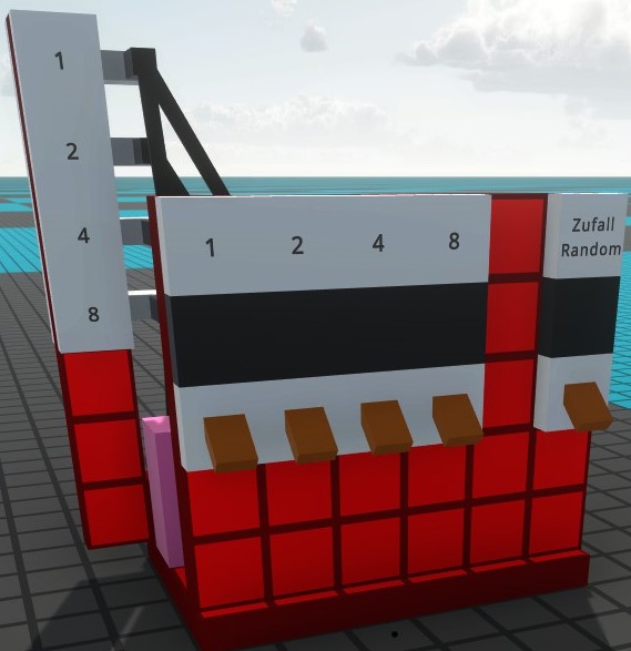
With the test station you can specify the 4 bits or run a random number generator:
The 4 bits are specified via switches.
The connection goes first to the lamps and then to the plugs.
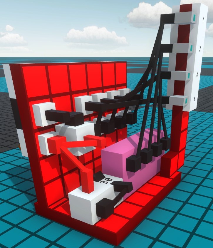
The random number generator requires 4 oracles, 1 delayer and an inverter:
A clock generator is built from the delay and the inverter.
First set the delay to 30 and then connect the output to the input of the inverter and then the output of the inverter to the input of the delay.
At Oracles you connect the inputs together and then with the output of the delay.
Then connects the output of the Oracle with the associated bit on the connector.
To switch the random number generator on and off you set a switch and turn it 180°, connect it to the inverter input of the clock generator.
The inverter next to the switch is for inverting the switch signal to the lamp.
This completes the test station.
It only has to be placed to the right of the 7 segment display, then you can test the display.
End
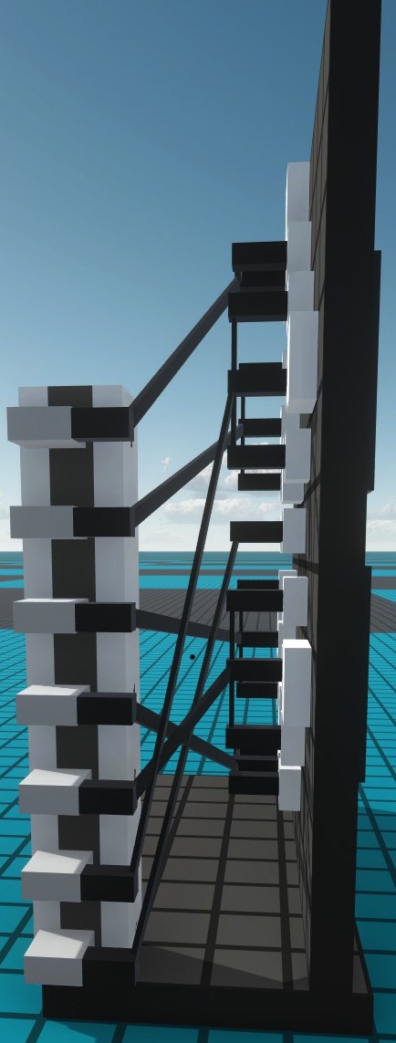
When you are full size and have the test station built it should now look like this from above.
Of course, this is just an example, you could also stack the address cards, for example.
There are of course other ways to control the 7 segment display, but this is the simplest and fastest solution
I hope you liked the guide and found it helpful.
Check out my other guide:
Logik Bausteine – [steamcommunity.com]
But that is still a work in progress and not in english in moment
Write me if you have any questions or comments.
I hope you enjoy the Guide we share about Logic World – 7 Segment Display with 4 Bits Addressing; if you think we forget to add or we should add more information, please let us know via commenting below! See you soon!
- All Logic World Posts List






Leave a Reply